CL86T(V4.0) Closed Loop Stepper Drive User Manual
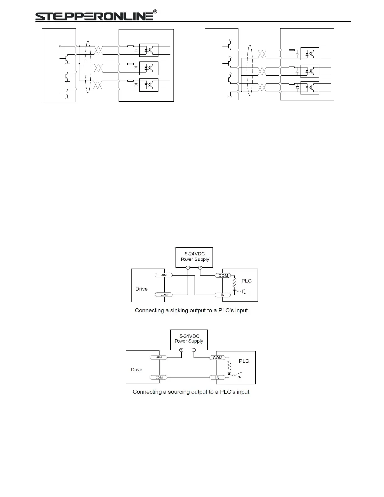
Figure 3: Connections to open-collector signal Figure 4: Connections to PNP signal
(Common-anode) (Common-cathode)
Notes:
(1) ENA signal is no-connected as default;
(2) ENA signal is no connected as default, and
ENA signal
is available for 5V~24V.
6.2 Fault Output Connection
When over voltage or over current protection happens, CL86T(V4.0) red status LED light will blink and the
impedance state between ALM+ and ALM- will change (from low to high or high to low depending on
configuration) and can thus be detected. Fault output connection is optional, and it can be connected either in
sinking or sourcing.
6.3 Brake Output Connection
This drive has a special brake output; it needs to drive the motor brake with a relay. The connection is below:
Drive
Controller
VCC
PUL-
PUL+
ENA-
PUL
DIR
ENABLE
DIR-
DIR+
ENA+
Drive
Controller
VCC
PUL-
PUL+
ENA-
PUL
DIR
ENABLE
DIR-
DIR+
ENA+