CL86T(V4.0) Closed Loop Stepper Drive User Manual
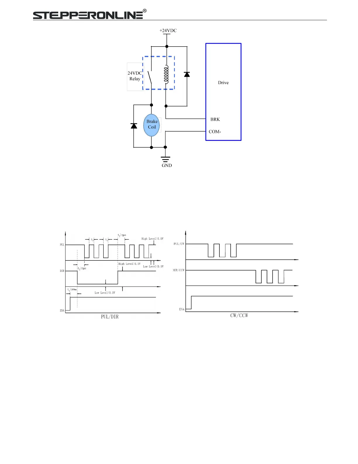
Figure 7:Brake output connection
7. Sequence Chart of Control Signals
In order to avoid some fault operations and deviations, PUL, DIR and ENA should abide by some rules,
shown as following diagram:
Figure 8: Sequence chart of control signals
Remark:
a) t1: ENA must be ahead of DIR by at least 200ms. Usually, ENA+ and ENA- are NC (not connected).
See “Connector P1 Configurations” for more information.
b) t2: DIR must be ahead of PUL effective edge by 2us to ensure correct direction;
c) t3: Pulse width not less than 1us;
d) t4: Low level width not less than 1us;
e) Duty cycle of PUL signal is recommended 50%.