EasyManua.ls Logo

StepperOnline CL86T - Switch Configurations; Rotating Switch Configurations; DIP Switch Configurations Overview; Micro Step Resolution (SW1-SW4)

StepperOnline CL86T
12 pages
To Next Page IconTo Next Page
To Previous Page IconTo Previous Page
Loading...
CL86T(V4.0) Closed Loop Stepper Drive User Manual
5
5. Switch Configurations
5.1 Rotating Switch Configurations
This rotating switch is used to set the peak current of the drive and motion gain, from the motor phase current
and application requirements.
Peak Current
Code
Velocity loop Ki
Position loop Kp
Velocity loop Kp
5.6A
0 (factory)
0
25
25
1
0
50
15
2
16
25
25
3
16
50
15
7.0A
4
0
25
25
5
0
50
15
6
0
100
5
7
16
25
25
8
16
50
15
9
16
100
5
8.0A
A
0
25
25
B
0
50
15
C
0
100
5
D
16
25
25
E
16
50
15
F
16
100
5
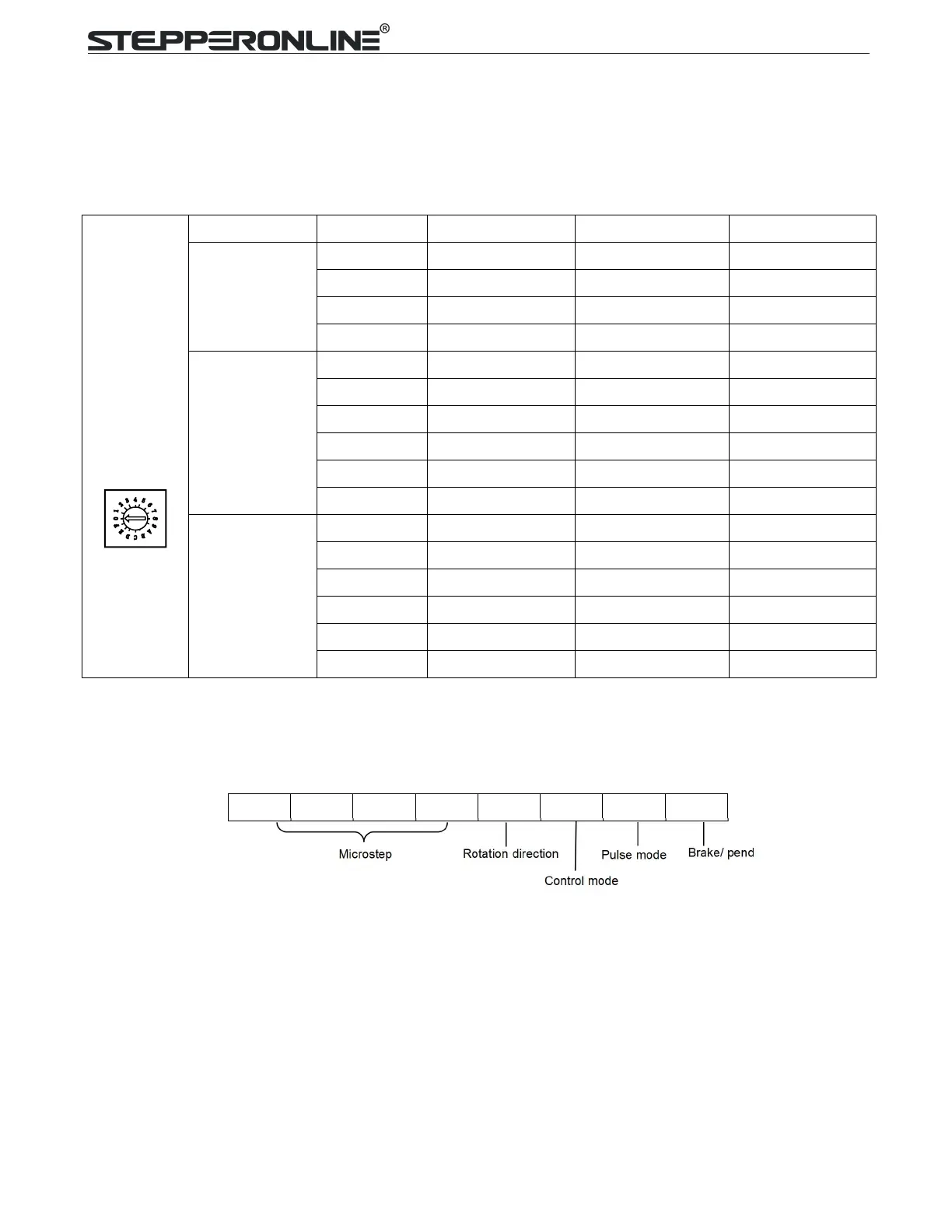
5.2 DIP Switch Configurations
The 8-bit is located on the side and used to configure settings of micro step resolution, output current, and
motor standstill
current as shown
below
Figure 2: DIP switches
5.2.1 Micro Step (SW1-SW4)
Each CL86T (V4.0) has 16 microstep settings which can be configured through DIP switches SW1, SW2,
SW3 and SW4. See the following table for detail.
SW1
SW2
SW3
SW4
SW5
SW6
SW7
SW8

Related product manuals