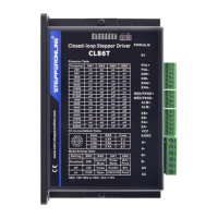
CL86T(V4.0) Closed Loop Stepper Drive User Manual
3. Connections and LED Indication
3.1 Control and Digital Output Connections
Pulse and Direction Connection:
(1) Optically isolated, high level 3.5-5V or 24V, low voltage 0-0.5V
(2) Maximum 500 KHz input frequency
(3) The width of PUL signal is at least 1.0μs, duty cycle is recommended 50%
(4) Single pulse (step & direction) or double pulse (CW/CCW) is set by DIP Switch
SW7
(5) DIR signal requires advance PUL signal minimum 2 μs in single pulse mode
(6) The factory setting of control signal voltage is 24V, must need to set 5V/24V
rotating switch if it is 5V
Enable Signals: Optional.
(1) Effective high level is 3.5-24V; Effective low level is 0-0.5V connection
(2) ENA signal requires advance DIR signal minimum 200ms in single pulse
mode, (default no connection)
Select brake output or pend output by switch 8, default as brake output
Max 30VDC/100mA
Notes: (1) Shielding control signal wires is suggested;
(2) To avoid/reduce interference, don’t tie control signal cables and power wires together;
(3) Brake output need to connect a relay and diode
3.2 Encoder Signals Input Connector
Encoder B+ input connection
Encoder B- input connection
Encoder A+ input connection
Encoder A- input connection
Encoder +5V voltage output connection