Sterling Power Products
Copyright
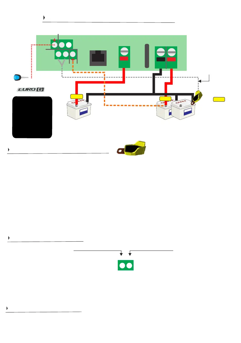
Engine Starter
Battery
(connected to alternator)
Important
NEGA
TIVES
should all be common.
DON'T USE CHASSIS
W
e recommend joining
the BB’
s neg. to the
starter battery negative.
For improved efficiency
.
House / Domestic /
Aux
Battery Bank
(arranged here as a 12V bank)
Temperature
Sensor
(T
S
A
Y
)
o
ptio
n
a
l
f
i
t
.
Polarity of wires into
(1)
and (2) does NOT
matter
.
Installation Diagram / all non Solar Models
BMS (1)
BMS (2)
Use BMS 1 - if your BMS trips and provides a 0V
(ground signal), then use BMS 1. This shall result in the
BB turning off. Once the BMS removes this trip status,
i.e. the 0V signal goes back to a +ve signal, the BB shall
start charging again.
Use BMS 2
- if your BMS trips
to
a +ve voltage (2V
-17V), then
use
BMS
2. This shall
result in the
BB turning of
f
when this
voltage is received. Once the BMS removes this trip status,
i.e. the +ve signal goes back to 0V signal, the BB shall start
charging
again.
BMS 1
status:
operational: 2-17V
trip voltage: 0V
BMS 2
status:
operational: 0V
trip voltage: 2V-17V
line to ignition
(recommended if vehicle is Euro 6)
Aux
Batt
out +
Engine
Batt.
input +
Com.
Neg.
BMS 2 (5)
BMS 1 (6)
Battery temp.
sensor (1,2)
Ignition
feed (4)
Upper
Lower
Remote
control
+
-
1 2 3
4 5 6
f u s e
+
5 6
fuse
fuse
6
BMS and remote features appear later
Temperature sensor cables are not polarity sensitive, install either way. If you wish to install, connect the temp
sensor to the negative of the domestic / aux. batteries.
When temperature sensor senses the temperature lower than 20Deg C the voltage shall go up on the
charger’s output and when the temperature is higher than 20Deg C the charge voltage shall drop. The rate is
18mV (0.018V) per Deg C or 0.018V / Deg C. If sensor temperature is at 10 Deg C the voltage elevation shall
be 0.018 x 10 = 0.18V. This shall explain why, in cooler climates / seasons you may see slightly elevated charge
voltage / voltage at your batteries. This is no concern. In warmer climates / seasons you shall see slightly lower
charge voltages. This voltage fluctuation is only with ‘lead acid style’ batteries. For lithium profiles, there is no
voltage fluctuation.
The temperature sensor shall trip the charger if the temperature at the battery >55DegC.
If the BB is in either lithium profiles the unit shall trip at 0DegC, if temp sensor is connected. This temperature
can be adjusted. If you do not want the 0DegC trip or any trip, please uninstall the temperature sensor.
remote voltage sense
compensates for
potentially long cable
runs to domestic
battery.
BMS connectors
Temperature sensor (part no. TSAY)
These
BMS connectors can also
be
used
as
simple
on/of
f
signal
connectors. If you wish
for
the BB to turn
of
f with a live
(+ve) signal
please
use
BMS
2.
If
you
wish
for
the BB to turn
of
f based on
a ground (0V)
signal,
use BMS 1. These signals do
not
have to
come
from
a BMS, they can come from any
source.
Fuse ratings
on Page 5
fuse
Remote voltage sense
The remote voltage sense is designed to achieve the correct charge voltage at the charging battery (house) itself.
There is often voltage drop across DC cabling, this sense feeds back to the BB what the charge voltage at the BB
should be in order to get the correct charge voltage at the battery. The sense cable, itself, carries no current, it can
be as thin as you can find. Please connect between (3) and the positive terminal of output battery.
 Loading...