EasyManua.ls Logo

Sterling Power BB1230 User Manual

Default Icon
19 pages
To Next Page IconTo Next Page
Page #1 background imageLoading...
Page #1 background image
Sterling Power Products
Copyright
STERLI
G
POWER
Pro Batt Ultra
Copyright © 2020
Sterling Power
December 2020 V4
BBS1230 - New to 2020
battery temp
sensor
TSAY
USERS MANUAL.
Sterling Power Products
H Charge
Float
In / Unit
Out / Rem
Batt.
V
12.2
Temp
Menu
Change
Volts
Select
Audible alarm on/off
hold > 3 sec
On / Off
hold>3 sec
Fault
Absorption
Cond.
Optional Remote
Instructions inside
BBURC
technology
4
D
U
:
L
R
A
A
T
I
B
G
L
I
E
D
:
:
D
C
I
E
S
M
I
A
G
N
N
Y
D
ProDigital
RoHS
compliant
Test Report Sheet
Each product gets uniquely tested and a report is generated.
This unique test report is present inside this box.
You must keep this test sheet in this box and keep this box safe.
This sheet should be present when the charger is being warranted.
English Manual
These instructions are for the & ( ) stripe BB modelsBLUE YELLOW solar
New
software V71+
+
+
+
+
+
+
Battery temp
sensor
Remote Voltage Sense
Remote
socket
ign
ctrl
Neg
+
Ignition
BMS (1)
BMS (2)
+
+
+
+
+
+
+
+
Battery temp
sensor
Remote Voltage Sense
Remote
socket
ign
ctrl
Neg
+
Ignition
BMS (1)
BMS (2)
+
+
Engine Starter
Battery
(connected to alternator)
House / Domestic / Aux
Battery Bank
(arranged here as a 12V bank)
fuse fuse
BB1 (master)
BB2 (slave)
150A rated cable
200A fuse
150A fuse
120A rated cable
input
output
60A rated cable
60A rated cable
ignition (paralleled)
+
BB1230 | BB122430
BB244860
BB1260 | BB122470 | BB123670
BB124870 | BB241235
Aux
Bat
out +
Engine
Batt.
input +
Solar Neg
Max V
31V
Com.
Neg.
BMS 2 (5)
BMS 1 (6)
Battery temp.
sensor (1,2)
Ignition
feed (4)
Remote
Voltage
sense (3)
Upper
Lower
Remote
control
Solar
Pos+
+ + +
- -
1 2 3
4 5 6
Output To
Aux Batt
Starter
Engine Bat.
House / Domestic / Aux / Bow thruster
fuse
50A
fuse
50A
MUST READ
For the majority of users, reading this paragraph should be sufficient for installation. The unit can be
installed by simply connecting it between an input and output battery, as depicted. The solar panel’s
positive and negative connectors go to the +ve and -ve connectors (BBS1230 model only) - voltage should
not exceed 31V (12V panel). The BB, by default, shall start charging when the starter input voltage exceeds
13.5V and switches off when the voltage drops below 13.3V (all models). The default charging profile is
14.4V abs. and 13.6V float - for sealed lead acid batteries (x2 for 24V | x3 for 36V | x4 for 48V). This means that
the vast amount of installations can be fitted out of the box without any adjustments. In certain
circumstances, when installing in a Euro 6 vehicle, we recommend using an ignition feed to the unit. When the
ignition is live, unit starts charging (may take up to 60 seconds). Please read the manual for additional information. If
in doubt, and installing on a New Euro 6+, use ignition feed. For info on BMS, remote sense, temp sensors and
remote control, please consult the manual. Solar charge shall operate when engine off and predominately go to the
leisure battery. There shall be a small 0.5A-1A back feed to the starting battery to keep it topped up, too. Maximum
wattage that can be harvested from the solar panels is 350W - 31V maximum and 16A maximum.
BBS1230 - New to 2020
Solar Panel up to 31V (nominal 12V rated) - do not exceed.
No limit to wattage, however, max harvest is ~350W
Negatives should all be common.
Use cable, do NOT use chassis.
Aux
Bat
out +
Engine
Batt.
input +
Com.
Neg.
Battery temp.
sensor (1,2)
Upper
Lower
Remote
control
+
-
1 2 3
4 5 6
f u s e
+
Starter
Engine Bat.
House / Domestic / Aux / Bow thruster
FUSE
FUSE
BMS 2 (5)
BMS 1 (6)
Ignition
feed (4)
ignition feed (4)
recommended for
Euro 6 vehicles (optional)
ignition feed (4)
recommended for
Euro 6 vehicles
(optional fit)
BB1230 layout
shall be slightly
Different
All BB models except solar
Question and Answer IconNeed help?

Do you have a question about the Sterling Power BB1230 and is the answer not in the manual?

Sterling Power BB1230 Specifications

General IconGeneral
BrandSterling Power
ModelBB1230
CategoryBattery Charger
LanguageEnglish

Summary

Test Report Sheet

Test Report Sheet Details

Details on the unique test report for each product and its importance for warranty.

Product Specifications

Technical Specifications Table

Detailed table of input/output voltages, current, IP rating, and dimensions for various models.

Legal and Safety Information

Manual Usage and Personnel Requirements

Guidance on manual usage, finding updates, and the need for qualified installation personnel.

Warranty and Liability Disclaimers

Details on warranty coverage, limitations, liability disclaimers, and product modification warnings.

General Safety and Maintenance Precautions

Safety symbols, general maintenance, installation precautions, and battery safety guidelines.

Front Panel Display I

Front Panel Display Annotation

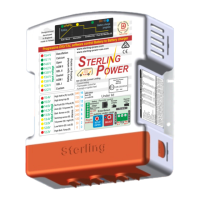
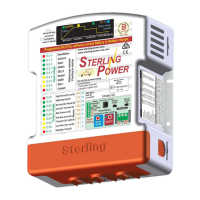
Detailed explanation of LEDs and their functions on the front panel display.

Front Panel LED Meanings

Explanation of the meaning of each LED indicator for voltage, status, and alarms.

Auxiliary Information Indicators

Information on ignition feed, solar power, and high voltage trip indicators.

Front Panel Display II

Under the Lid Connections

Details of connectors and components located under the red end cap.

Physical Dimensions

Physical dimensions of the BB units in millimeters.

Cables and Fuses Guidelines

Guideline for selecting appropriate cable sizes and fuse ratings for different BB models.

Installation Diagram (Non-Solar)

Important Negatives Connection

Guidance on common negative connections and avoiding chassis connection for efficiency.

Temperature Sensor Installation

Instructions for installing the temperature sensor and its effect on charge voltage.

BMS Connectors Explained

Explanation of BMS 1 and BMS 2 connectors for shutdown signals and simple on/off control.

Remote Voltage Sense Connection

How to connect the remote voltage sense to compensate for voltage drop in cabling.

Installation Diagram (Solar BBS1230)

Solar Charger Operation Note

Clarification that solar and BB chargers do not work simultaneously; they operate independently.

Important Negatives Connection

Guidance on common negative connections and avoiding chassis connection for improved performance.

Lithium Battery Installation

Changing Battery Type Presets

How to select and change between different lithium battery presets (I and II).

External BMS Shutdown Procedure

Using external BMS signals (BMS 1/2) to control BB charging for lithium batteries.

Internal BMS Shutdown Considerations

How internal BMS in lithium batteries can affect BB operation, especially at low temperatures.

0 Deg C Trip Setting

Setting the BB to stop charging at 0 Deg C when using lithium batteries and a temp sensor.

Automatic and Ignition Feed Modes

Automatic Activation Explained

Explanation of default automatic operation based on input voltage sensing.

Two Ignition Feed Modes

Details on two ignition feed modes for controlling BB operation with vehicle ignition.

First Time Use and Initial Setup

Initial Startup Sequence and Faults

Understanding initial startup behavior, LED indicators, and common fault indications.

Battery Type Selection During Startup

How to select the correct battery type during the initial startup process.

Voltage Range Interpretation and Correction

Interpreting out-of-range voltages and correcting low/high output voltage issues.

Factory Reset and Status Viewing

Procedures for returning to factory defaults and viewing the charger's operational status.

Guide to Buttons and Operations

Button Functions Overview

Summary of functions accessed by pressing SETUP or SELECT buttons with varying flashes.

Factory Reset Procedure

Steps to perform a factory reset to restore default settings.

Force Options and Advanced Settings

Buzzer Control and Software Information

Controlling the buzzer and accessing the unit's software version.

Operational Mode Activation

Enabling specific modes like live voltage output, pure ignition feed, or maintenance mode.

Voltage and Timer Adjustments

Configuring operational voltages, temperature compensation, and regenerative braking timer.

Further Force Options and Controls

Float, Power Limiting, and Standby Modes

Forcing float, half power, or standby modes for specific operational needs.

Charger Power Off and Installer Lock

Turning the charger off and locking settings for installers.

Model-Specific Feature Control

Controlling solar charging or BB charging on the BBS1230 model.

Custom Settings Configuration

Custom Battery Type Setting

Expert guide to setting custom charge profiles and parameters.

Adjusting Charge Voltages

Setting custom fast charge, conditioning, and float voltages.

Absorption Time Factor Adjustment

Adjusting the absorption time factor (ATF) and minimum/maximum times.

Understanding Absorption Time Factor (ATF)

Explanation of how the Absorption Time Factor (ATF) works and is calculated.

Custom Settings Continuation

Maximum Absorption Time Factor

Setting the maximum absorption time in custom charge profiles.

Temperature Sensor Trip Adjustment

Setting the temperature trip point for the charger in custom configurations.

Adjustment of Operational Voltages

Adjusting linked operational voltages (cutoff, charging, low voltage trip) as a block.

Remote Control Operations

Remote Control Buttons Explained

Description of each button and its function on the remote control unit.

Setup Menu Navigation Guide

Detailed guide on navigating the remote control's setup menu and its options.

Remote Error Codes

List and explanation of error codes displayed by the remote control.

Front LED Information Panel

LED Zone Breakdown

Explanation of the different zones (1-4) on the front panel and their primary functions.

Reading Voltages and Operation

How to interpret LED indications for input/output voltages and normal operation.

Solar Panel Voltage Indication

How Zone 4 LEDs indicate solar input voltage when solar power is live.

Fault Finding and Troubleshooting

Initial Wiring Checks

Ensuring correct wiring, common negatives, and checking voltages before troubleshooting.

How to Test Charging

Steps to verify if the BB is actively charging by measuring input and output voltages.

Troubleshooting Low Output Voltage

Troubleshooting steps for low output voltage scenarios.

Troubleshooting Low Input Voltage

Troubleshooting steps for low input voltage, including alternator and battery issues.

Interpreting LED Fault Indicators

Interpreting specific LED flashes (e.g., red, yellow) to diagnose faults like over/under voltage or temperature.

Customer Service and Warranty

Product Warranty Details

Information on the 2-year limited factory warranty, coverage, and exclusions.

Warranty Claim Procedure

Steps for making a warranty claim, including required proof of purchase and shipping costs.

Contact Information and Support

Contact details for customer service and warranty claims in the USA and England.

Related product manuals