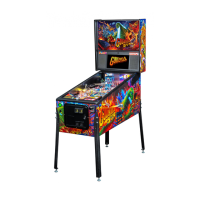
GODZILLA
SERVICE AND OPERATION MANUAL
1-800-KICKERS - parts.service@sternpinball.com
www.sternpinball.com - facebook.com/sternpinball
MANUAL #780-50T6-00
GODZILLA LE #500-55T6-01
GODZILLA PREMIUM #500-55T7-01
SERVICE AND OPERATION MANUAL
Games congured for North America operate on 60 cycle electricity only. These games will not operate in countries with 50 cycle electricity (Europe, UK, Australia).
WARNING
IMPORTANT HEALTH WARNING: PHOTOSENSITIVE SEIZURES - A very small percentage of people may experience a seizure when exposed to certain visual images,
including ashing lights or patterns. Even people with no history of seizures of epilepsy may have an undiagnosed condition that can cause “photosensitive epileptic
seizures” due to certain visual images, ashing lights or patterns. Symptoms can include lightheadedness, altered vision, eye or face twitching, jerking or shaking of arms or
legs, disorientation, confusion, momentary loss of awareness, and loss of consciousness or convulsions that can lead to injury from falling down or striking nearby objects.
IMMEDIATELY STOP PLAYING AND CONSULT A DOCTOR IF YOU EXPERIENCE ANY OF THESE SYMPTOMS.
Stern Pinball machines are assembled in Elk Grove Village, Illinois, USA. Stern Pinball has inspected each game element to ensure it meets our quality standards.
Each pinball machine has unique characteristics that make it a one-of-a-kind American made product. Each will have variations in appearance resulting from differences
in the machine’s particular wood parts, individual printed art and mechanical assemblies. No playeld is perfectly at and varies depending on the season. Game play will
result in playeld dimpling as the harder steel ball contacts the wood and coating; over time multiple dimples will blend to make them less noticeable. Normal plastic insert
crazing (tiny stress cracks) and ghosting (small cloudy areas around insert edges) are often seen in pinball machines, due to a combination of plastic mold stress, pushing of
inserts into purposely undersized holes, and heating and breaking of inserts’ plastic “skin” when the playeld is sanded.
ATTENTION! IMPORTANT WARRANTY INFORMATION
The electronics system, node network architecture, mechanical devices and associated software control systems in this pinball machine are designed to work with genuine
Stern Pinball accessories and devices.
Installation of non-authorized accessories, lamps, LED’s, motors or other devices or modication of electro-mechanical devices may damage the system and will void your
warranty.
 Loading...