Do you have a question about the Stern Pinball JAWS and is the answer not in the manual?
Guide for unpacking and initial setup of the pinball machine.
Instructions for positioning, leveling, and completing the final setup.
Details on general game adjustments available through the service menu.
Game-specific adjustments to customize gameplay features.
Monthly maintenance tasks including cleaning and checks.
Comprehensive maintenance procedures for long-term care.
Introduction to the SPIKE pinball system architecture.
Explanation of the SPIKE node bus connection standards.
Information on assigning addresses to SPIKE nodes.
Identification of common SPIKE node boards and their part numbers.
Reference for various SPIKE node boards used in the game.
Detailed list of game drivers, their connections, and part numbers.
Comprehensive list of game switches and their wiring details.
Detailed list of game lights, their locations, and wiring.
Information on motor control, wiring, and operation.
Pinout details and switch mapping for the SPIKE-2 CPU Node 0.
Pinout details for the Cabinet Node 1.
Pinout details for the lower playfield 48V driver board.
Pinout details for the upper playfield 48V driver board.
Pinout details for the center LED board.
Pinout details for the lower mid-right LED board.
Pinout details for the 3-LED board.
Pinout details for another 3-LED board.
Pinout details for the billboard 4-LED board.
Pinout details for the left LED board.
Pinout details for RGB and White LED boards.
Pinout details for the shark fin LED board.
Pinout details for the serial motor driver board.
Pinout details for the serial 16-LED board.
Pinout details for the trough serial opto receiver.
Details connections for the main power supply unit.
Pinout details for the power distribution board.
Important safety warnings, compliance, and legal information.
| Brand | Stern Pinball |
|---|---|
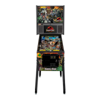
| Model | JAWS |
| Category | Pinball Machine |
| Language | English |