Do you have a question about the stertil-KONI Freedomlift SK 2055 and is the answer not in the manual?
| Brand | stertil-KONI |
|---|---|
| Model | Freedomlift SK 2055 |
| Category | Lifting Systems |
| Language | English |
Instructions for keeping the manual accessible near the machine.
Refers to order confirmation for guarantee and liability terms.
Procedures for machine relocation or ownership transfer require contact with manufacturer.
Details changes made in different versions of the manual.
Lists registered trademarks of Stertil B.V. or its suppliers.
Manual contains warnings and safety notices for safe operation.
Contact information for Stertil B.V. service and support.
Precautions for safe operation of the Freedomlift.
Identifies safety and protection signs used on the Freedomlift.
Overview of the lift's built-in safety mechanisms.
Outlines necessary qualifications and knowledge for service personnel.
Recommends specific training levels for operators, supervisors, and engineers.
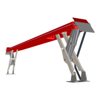
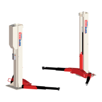
Provides detailed technical data for the lift models.
Information for identifying the product, found on the type plate.
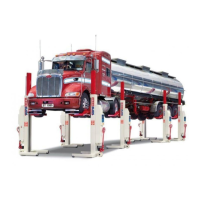
Step-by-step guide for setting up the Freedomlift.
Requirements for concrete floor, thickness, quality, and anchors.
Details on required power supply cables and connections.
Instructions for safely unpacking and positioning the lift posts.
Steps for connecting hydraulic hoses and electrical cables.
Guide for attaching the lift's vehicle support arms.
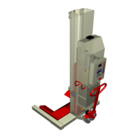
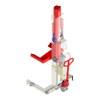
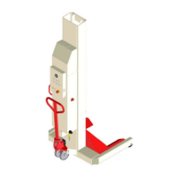
Identifies buttons and indicators on the main control panel.
Explains lift behavior during initial operation and phase checks.
Describes how the elevation control system monitors lift status.
Details how the system corrects differences in post height.
Steps to ensure correct initial setup before operation.
Procedures for bleeding cylinders and adjusting guide pieces.
Instructions for verifying and adjusting the pawl mechanism.
How to program the lift's maximum lifting height.
Setting up automatic control of the lift's lights.
Programming the automatic foot protection safety feature.
Adjusting the master/slave correction valve operation.
Adjusting safe limit parameters for lift operation.
Disabling potentiometers for checking lift function.
Aligning resistance tolerances for potentiometers.
Activating the optional second control box.
Verifying the pawls engage correctly with the ratchet bar.
Testing automatic stop features during lowering.
Verifying safety system disables functions when required.
Testing the lift's automatic self-correction feature.
Setting up the audible alarm for foot protection.
Procedure to remove air from hydraulic cylinders.
Final checks after installation before full load testing.
Performing static and dynamic tests with a full load.
Explains the purpose of preventive and corrective maintenance.
General awareness and safety points before performing maintenance.
Overview of required maintenance actions for operators and engineers.
Lubrication schedule and points for the lift.
Procedure for changing the hydraulic oil approximately every two years.
Regular cleaning procedures for various lift components.
Checks to perform during a visual inspection of the lift.
Step-by-step guide for removing and mounting a lift cylinder.
Manual procedure for lowering the lift in an emergency.
Lists error codes displayed on the control panel and their solutions.
Identifies common issues and provides solutions.
Contact information for further assistance from Stertil B.V.
Overview of major assemblies and their parts.
Detailed breakdown and part numbers for Column 1.
Detailed breakdown and part numbers for Column 2.
Detailed breakdown and part numbers for the guide block assembly.
Detailed breakdown and part numbers for the double telescopic arm.
Detailed breakdown and part numbers for the telescopic arm.
Detailed breakdown and part numbers for the flex arm.
Part list for specific double telescopic arms.
Detailed breakdown of arm connection parts.
Detailed breakdown of flex arm connection parts.
Detailed breakdown and part numbers for the hydraulic cylinder.
Detailed breakdown and part numbers for the hydraulic unit.
Detailed breakdown of connecting lines and fittings.
Detailed breakdown and part numbers for the control box.
Overview of assembly variants and optional components.
Schematic diagram of the hydraulic system.
Wiring diagram for 3 x 230V electrical configuration.
Wiring diagram for 3 x 400V electrical configuration.
Key for electrical diagram components and control box functions.
Dimensional drawings for SK 2055 with extended flex arms.
Dimensional drawings for SK 2055 with 3-piece arms.
Dimensional drawings for SK 2070/2090 with 2-piece arms.
Dimensional drawings for SK 2070/2090 with 3-piece arms.