Do you have a question about the STEYR MOTORS M0164M40 and is the answer not in the manual?
General information and remarks about STEYR marine engines.
Details essential specifications including fuel and oil requirements for optimal engine performance.
Outlines maintenance schedules and troubleshooting procedures for common engine issues.
Covers engine management systems, diagnostics, and operational guidelines.
Sets standards for spare parts and workshop practices to ensure quality repairs.
Lists necessary operating materials and provides guidance on proper disposal methods.
Emphasizes critical safety instructions and precautions for handling the engine and its systems.
Specifies torque values for critical fasteners to ensure proper assembly and function.
Defines acceptable wear limits for engine components to maintain performance and longevity.
Covers procedures for setting engine timing and replacing engine mounts.
Details operations related to the engine's cylinder block, including valve replacement.
Describes procedures for replacing the crankshaft, bearings, and vibration damper.
Covers tasks related to the flywheel and its housing, including replacement.
Outlines procedures for dismantling and assembling pistons and connecting rods.
Details operations related to the camshaft, housing, and valve train components.
Covers disassembly and assembly of the engine housing, oil pump, and suction pipe.
Describes procedures for removing and assembling the intercooler.
Details the removal and installation of the auxiliary drive or Power Take-Off (PTO).
Covers procedures for replacing and repairing the engine oil cooler.
Refers to procedures for servicing the exhaust manifold, seals, and heat exchanger.
Provides instructions for replacing the torsion coupling for different engine types.
Provides a functional overview of the fuel system and its components.
Covers the replacement and adjustment procedures for the fuel pump, unit injectors, and lines.
Details the process for changing the air filter on STEYR marine engines.
Outlines procedures for replacing the turbocharger and checking its bearing clearance.
Covers the removal, installation, and replacement of the control solenoid and related sensors.
Provides instructions on how to change the fuel filter to prevent system contamination.
Details the procedure for replacing glow plugs, including torque specifications.
Explains how to measure engine compression pressure using specialized tools.
Guides on performing manual injection tests and checking for air bubbles in the fuel system.
Covers the replacement of the Hi-Riser, including disassembly and assembly steps.
Explains how to measure exhaust backpressure to ensure optimal engine performance.
Provides a functional overview of the engine's cooling circuits, including raw water and closed coolant systems.
Details the components of the cooling system's heat exchange and expansion systems.
Covers maintenance and replacement procedures for coolant pipes, hoses, and the thermostat.
Outlines the procedures for exchanging and installing the engine's coolant circulating pump.
Details the process for exchanging the Poly-V-belt on 4-cylinder engines.
Covers the exchange and adjustment of V-belts for alternators, servopumps, and raw water pumps.
Provides instructions for exchanging the raw water pump for different engine versions.
Details checks for air in the closed engine cooling system and troubleshooting coolant loss.
Covers general information on wiring, cable numbers, and principal functions according to DIN 72 552.
Details procedures for adjusting belt tension and replacing the alternator.
Outlines the steps for replacing the starter motor and checking its components.
Provides information on battery cable sizing and general wiring harness considerations.
Illustrates the E-box base plate components and connection details for specific engine numbers.
Shows E-box base plate components and connections for later engine models and SOLAS versions.
Details the wiring harness designations and their functions for specific engine numbers.
Lists wiring harness designations and functions for later engine models and SOLAS versions.
Provides general information on the Electronic Engine Management System (EMS) and diagnostic procedures.
Explains the functions of the EMS, including engine control, self-diagnostics, and power reduction.
Details the EMS diagnostic capabilities, fault storage, and error code retrieval.
Explains how to read stored error codes using a diagnostic tool or check engine lamp.
Guides on selecting, indicating, and clearing memorized sensor and circuit faults from the EMS.
Lists common failure codes, involved devices, and possible causes for engine system faults.
Provides instructions for replacing automatic circuit breakers and standard fuses.
Details the pin assignments and explanations for the J1 connector.
Shows the connection details for the A5 and X5 connectors, including pin assignments and component descriptions.
Illustrates the correct procedure for fitting the main connector "J1".
Describes the components and indicators of the standard instrument panel.
Explains normal operating status indications and system checks for the instrument panel.
Details error indications on the instrument panel for various fault conditions.
Describes the instrument panel layout and indicators specifically for SOLAS compliant units.
Explains instrument indications during normal operation for SOLAS compliant systems.
Details error indications on the instrument panel for SOLAS systems under various fault conditions.
Lists components and descriptions for the 6-cylinder instrument panel wiring harness (old version).
Describes the wiring harness for 4/6 cylinder marine engines (current version).
Provides an overview of sender and sensor components for 4-cylinder engines.
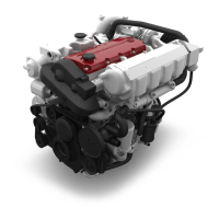
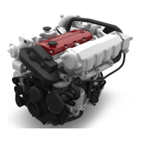
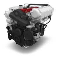
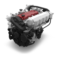
Identifies and describes components and their locations on the 4-cylinder engine.
Identifies and describes components and their locations on the 6-cylinder engine.
Guides on calibrating the rack position sensor after component replacement or adjustment.
Covers the replacement procedures for various engine sensors including temperature, speed, and pressure.
Details methods for checking the functionality of various sensors and switches.
Provides information on battery types, acid tests, capacity, and maintenance procedures.
Covers battery testing, capacity checks, and essential maintenance for long service life.
| Engine Type | Diesel |
|---|---|
| Number of Cylinders | 4 |
| Displacement | 1.6 L |
| Cooling System | Liquid cooled |
| Aspiration | Turbocharged |
| Fuel System | Common Rail |
| Cylinders | In-line |