Do you have a question about the STEYR MOTORS M084K32 and is the answer not in the manual?
Details regarding warranty claims, registration cards, and pre-delivery inspection logs.
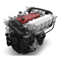
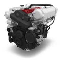
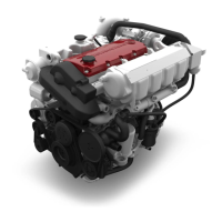
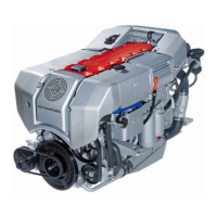
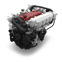
Detailed breakdown of engine components including timing, cylinder block, crankshaft, and valve gear.
Components and procedures related to the fuel pump, unit injectors, lines, air filter, turbocharger, and control solenoid.
Procedures for checking and replacing components of the cooling system, including pumps, thermostats, and heat exchangers.
Information on the alternator, starter motor, wiring harnesses, electronics, instrument panel, and sensors.
Troubleshooting guide for common engine symptoms, identifying possible causes, and recommended actions.
Explanation of EMS functions, self-diagnostics, power reduction, and data storage for maintenance.
How the EMS performs self-tests, checks sensors, and stores/retrieves error codes.
General information on personnel knowledge, training, and hazard awareness during repair works.
First aid measures for accidental contact with hazardous materials (skin, eyes, swallowing).
Specific tightening torques for engine components like camshaft housing, connecting rods, and main bearings.
Specific adjustment procedures and values for engine timing, belt tension, fuel delivery, and valve clearance.
Procedures for engine timing adjustment, crankshaft locking, and engine mount replacement.
Procedures for replacing the crankshaft, bearings, and vibration damper.
Procedures for replacing camshaft housing, valve stem gaskets, control rack, camshaft, and valve gear.
Overview of the fuel system's functionality, including fuel flow, pressure regulation, and pipe specifications.
Procedures for replacing the fuel pump, unit injector, and associated lines, including disassembly and assembly.
Procedures for replacing the turbocharger and checking bearing clearance.
Procedures for removing, installing, and replacing the control solenoid and related sensors.
Procedure for changing the fuel filter, including system ventilation and leak checks.
Method for measuring engine compression pressure, including necessary tools and expected values.
Procedures for checking the fuel system, including manual injection tests and air bubble detection.
Overview of the cooling system's functional description, detailing raw water and closed coolant circuits.
Detailed description of the raw water flow path, pump operation, and system components.
Explanation of the closed coolant circuit's circulation, thermostat operation, and heat exchanger function.
Troubleshooting guide for identifying and resolving problems within the cooling system.
Explanation of EMS functions, self-diagnostics, power reduction, and data storage.
How the EMS performs self-tests, checks sensors, and stores/retrieves error codes.
Procedure for entering the error code indication mode and reading stored faults.
Steps for selecting, displaying, and clearing stored error codes from the EMS.
| Number of Cylinders | 4 |
|---|---|
| Fuel System | Common rail direct injection |
| Emission Standard | EU Stage IIIA |
| Engine Type | Diesel |
| Cooling System | Liquid-cooled |