INSTALLATION
Installation
www.stiebel-eltron.com HPG-I (C)S Premium | 13
9.7 Venting the heating system
D0000036346
1
1 Automatic air vent valve
f Vent the pipework by pulling up the red cap on the air vent
valve.
f Close the air vent valve after the venting process.
9.8 DHW heating
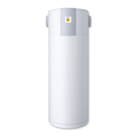
For DHW heating, a DHW cylinder with an internal indirect coil is
required. The minimum coil surface area required is 3m².
An integral 3-way valve is integrated in the appliance for switching
between the DHW heating circuit and the central heating circuit.
f Thoroughly flush the pipework before connecting the heat
pump. Foreign bodies, such as rust, sand and sealant, can
impair the operational reliability of the heat pump. We rec-
ommend installing our filter assembly in the DHW heating
circuit (see chapter "Appliance description/ Accessories").
f Connect the DHW flow of the appliance to the upper heat
exchanger coil connection of the DHW cylinder (see "Specifi-
cation/ Dimensions and connections").
f Connect the DHW return of the appliance to the lower heat
exchanger coil connection of the DHW cylinder (see "Specifi-
cation/ Dimensions and connections").
Note
If no DHW heating is being connected, connections e22
(cylinder flow ) and e23 (cylinder return) are to be hy-
draulically interconnected.
9.9 Operation with buffer cylinder
f Install the supplied TAFPT immersion/contact sensor.
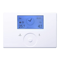
f Connect the sensor to the heat pump manager.
f Set the parameter on the heat pump manager.
Parameter Setting
BUFFER OPERATION (SETTINGS/ HEATING/ STANDARD
SETTINGS)
ON
HPG-I CS Premium
For cooling in combination with a buffer cylinder, an additional
TAF PT immersion/ contact sensor is required.
f Install the sensor in the buffer cylinder flow.
f Connect the sensor to the heat pump manager.
9.10 Fitting the push-fit connectors
Note
The plastic push-fit connectors are not suitable for instal-
lation in the DHW line.
f Only install the push-fit connectors in the heating or
brine circuits.
!
Material losses
f Tighten the screw cap of the push-fit connector by
hand. Never use a tool.
Material losses
To ensure the push-fit connector is held securely, pipes
with a surface hardness >225HV (e.g. stainless steel)
must have a groove.
f Using a pipe cutter, cut a groove (depth ap-
prox.0.1mm) at a defined distance from the end of
the pipe.
- Pipe diameter 22mm: 17±0.5mm
- Pipe diameter 28mm: 21±0.5mm
!
Material losses
Support sleeves are required when using plastic pipes.
D0000061240
f Remove the protective grey caps from the push-fit connec-
tors.
How the push-fit connectors work
The push-fit connectors are equipped with a retainer with stain-
less steel serrations and an O-ring for sealing. In addition, the
push-fit connectors are equipped with the "twist and lock" func-
tion. Simply turning the screw cap by hand will secure the pipe
in the connector and push the O-ring against the pipe to seal it.
 Loading...
