INSTALLATION
Preparation
www.stiebel-eltron.com HPG-I (C)S Premium | 7
8. Preparation
8.1 Safety concept
Never cover the appliance
f Keep the discharge and intake apertures clear.
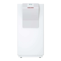
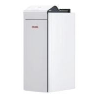
D0000099765
1
2
1 Discharge aperture
2 Intake aperture
A fan is installed in the appliance, which generates a negative
pressure in the device. If the negative pressure can no longer be
built up (damaged sealing tape), the safety pressure cell shuts
down the appliance. A message appears in the heat pump man-
ager.
Unit Value
Minimum negative pres-
sure
Pa 30
f Replace the sealing tape if required.
In the event of a leak, the fan mixes the refrigerant gas into the
air in the room sufficiently.
f Maintain the minimum installation area of the installation
room.
Minimum installation area
[m²]
HPG-I 04 (C)S Premium HPG-I 12 (C)S Premium
HPG-I 06 (C)S Premium HPG-I 15 (C)S Premium
HPG-I 08 (C)S Premium
6.0 8.0
Increasing the minimum installation area
If the minimum installation area requirement cannot be met in
the installation room, the installation room can be connected to
a neighbouring room via ventilation apertures. The ventilation
apertures must be located near the ceiling and the floor. If the
ceiling is suspended and there is no wall to the next room, the
upper ventilation aperture can be dispensed with.
≥
20
≥
20
100
200
300
≥
1500
50%
Anv
50%
Anv
D0000101711
- The ventilation apertures must not be closed.
- The upper edge of the lower ventilation aperture must be no
more than 300mm above floor level.
- 50% of the required ventilation aperture area must be less
than 200mm above floor level.
- The lower edge of the lower ventilation aperture must be no
more than 100mm above floor level.
- The ventilation aperture between the rooms must be at least
20mm wide.
- A second ventilation aperture is required. The ventilation ap-
erture must be no less than 50% of the required ventilation
aperture area. The lower edge of the ventilation aperture
must be at least 1500mm above floor level.
f Calculate the area of the ventilation apertures.
Anv =
m
c
- (0,4335 * A)
50,3
D0000095347
A Room area [m²]
Anv Required aperture surface [m²]
m
c
Refrigerant charge [kg]
f Install ventilation apertures corresponding to the calculated
area.
8.2 Installation site
!
Material losses
f Install the appliance only in rooms without a con-
stant ignition source (e.g. open flames, a live gas
appliance or an electric heater) or without open flue
boilers.
Note
The appliance is designed for indoor installation, except
in damp areas.
f Never install the appliance directly below or next to bed-
rooms.
f Route the pipe outlets through walls and ceilings with struc-
ture-borne noise insulation.
 Loading...