5.4 Electrical connection
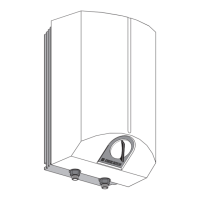
» Remove the bottom cap from the device by drawing off the re-
gulator button and removing the screws
G
.
» Electrical connection lead
H
.
5.4.1 Electrical circuit diagram
K
1 Thermostat
2 Safety temperature limiter
3 Pressure switch for signal anode
4 Heat content display
5 Plug distributor for N-lead
6 Terminal for power switchover
5.4.2 Connection variant
L
» Connect the power rating required in accordance with the con-
nection example and, if appropriate, replug the terminal bridge
(1).
5.5 Temperature selection limitation
G
For:
— Greater safety against scalding
— Less energy consumption
— Less limescale formation
— The temperature can be limited.
a Adjustment possibility of the temperature limitation
b Customer to prepare position for
5.6 Installation conclusion
» Mark the connection power and voltage on the device rating
plate with a ball-point pen.
» Place the bottom flap in position and secure it with screws
G
.
» Press the temperature selector button into position
G
.
5.7 First start-up
(may only be carried out by a qualified installer)
»
1
2
3
4
5
6
7
8
10
11
12
13
14
15
16
17
18
19
20
21
22
23
24
9
Fill the unit, deaerate it, and flush it through thoroughly!
»
1
2
3
4
5
6
7
8
10
11
12
13
14
15
16
17
18
19
20
21
22
23
24
9
Turn temperature selector switch to the right as far as the
stop!
»
1
2
3
4
5
6
7
8
10
11
12
13
14
15
16
17
18
19
20
21
22
23
24
9
Switch on mains electricity supply!
»
1
2
3
4
5
6
7
8
10
11
12
13
14
15
16
17
18
19
20
21
22
23
24
9
Check the operation of the appliance!
»
1
2
3
4
5
6
7
8
10
11
12
13
14
15
16
17
18
19
20
21
22
23
24
9
Check the safety group for functional performance!
»
1
2
3
4
5
6
7
8
10
11
12
13
14
15
16
17
18
19
20
21
22
23
24
9
Check the T&P valve for tightness.
Delivery status:
» At temperatures of below - 15 °C (e.g. transportation/storage)
the safety thermal cut-out may trip. Press the reset button
(
D
12).
Handing over the unit:
Explain the function of the unit to the users and familiarise them
with its use.
Important note:
Advise the users about possible hazards (such as scalding).
5.8 Maintenance
» When carrying out any work, disconnect all poles from the mains
supply.
» Check the safety group regularly.
» Descale the element only after dismantling. Do not treat the
reservoir surface and parasitic current anode with descaling
agents.
Safety device
» Regulator-limiter combination immersion depths
J
:
a - Limiter sensor
b - Regulator sensor
Draining the storage water heater cylinder
» Before draining the cylinder, disconnect the unit from the mains
supply.
» Close the isolating valve in the cold water feed line.
» Open the hot water fittings fully at all draw-off points.
» Unscrew the cap from the drainage nozzle (
D
10).
Risk of scalding or burning!
Hot water may come out during draining.
» The corrosion protection resistor
I
on the insulating
plate must not be damaged or removed during servicing
work. When replacing the corrosion protection resistor the
assembly is to be re-established in the correct manner.
a Copper heating element
b Insulating plate
c Pressure plate
d Corrosion protection resistor
» Check the signal anode and replace it as soon as the „SERVICE
ANODE“ signal lamp on the operating panel lights up. When
replacing the anode, it is essential for the pressure switch to be
screwed in tight.
 Loading...