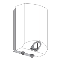
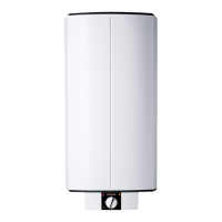
5.1 Structure of the device
A
-
D
1 Heating element
2 Service anode
– SH 30 S (GB)- M 8: Replace with heating element fitting
– SH 50 - 150 S (GB) - G 19.05 (¾"): Replace without heating
element fitting
3 Pressure switch for service anode
4 Combined thermostat and high-temperature cut-out
4a High temperature cut-out reset button (accessible from
the front)
5 Electronic stored heat display
6 Heating element flange
7 Gasket
8 Drain valve and hose connector G 19.05 (¾")
9 Pipe connection
10 Cable feed holes
11 Cold water inlet
12 Cylinder
13 Insulation
14 Outlet pipe
15 Teperature / pressure relief valve
16 Upper wall support *
17 Lower wall support (only on Model SH 120 S (GB) and
SH 150 S (GB) *
18 Protective caps
* For screws dia. 12 mm provided by customer
5.2 Installation location
» In an area not subject to the risk of freezing.
» Install close to the water tap.
5.3 Unit installation
E
5.3.1 Fit the suspension bracket
» Select the securing material to suit the strength of the wall.
With SH120S(GB) and SH150S(GB), two suspension brackets
are required.
» Any unevenness in the wall is to be compensated for by the
spacer elements provided (a. approx. 5mm thick).
» Install in a vertical position; see
D
.
» Push the cover caps onto the suspension bracket
E
(b).
5.3.2 Fitting the water connection and safety assembly
!
Risk of damage
Carry out all water connection and installation work
in accordance with regulations.
» If the static pressure is above 0.6 MPa, you must fit a pressure
reducing valve. A pressure reducing valve is not part of the
standard delivery and must be installed prior to proceeding with
the following installation.
» Flush the pipework thoroughly.
See chapter „Specification / Hydraulic diagram“ for general ar-
rangement in schematic form. You can fit the safety assembly in
various positions to suit the space available but it must be placed
in the same order as shown. The safety assembly provided in the
pack is fitted to the cold water supply with the exception of the
T&P valve which is fitted at the top of the DHW cylinder.
» To obtain a balanced water pressure in the cold water and DHW
lines, position the cold water outlet directly on the outlet side of
the pressure relief valve.
» The T&P valve should not respond under normal operating con-
ditions as the expansion vessel will accommodate the water as
it expands during the heating process.
» Check the pre-charge pressure of the expansion vessel and,
where appropriate, regulate it to 0.35 MPa.
» Run the safety relief valve outlet and that of the T&P valve to a
drain via a tundish. The purpose of the tundish is to let water
be seen should these valves respond. The outlet pipe should not
exceed 9 metres in length without forming an air break, i.e. tun-
dish. The pipe must fall continuously throughout its length with
no additional 90° bends. It must be heat resistant and discharge
to a safe visible position. The pipe diameter must not be smaller
than the valve outlet. The two discharge pipes can be joined to-
gether at the point of discharge into a single tundish if required.
Key to schematic diagram
F
1 Discharge below fixed grate
2 Cold water supply
3 Shut-off valve
4 Line strainer
5 Pressure relief valve
6 Balanced pressure; cold water outlet
7 Check valve
8 Safety assembly
9 Tundish
10 Metal discharge pipe (D2) from tundish, with continuous fall
11 Equipotential bond
12 Drain valve
13 Immersion heater, thermostat and high limit safety cut-out
14 Anode
15 Cylinder
16 DHW outlet
17 T&P valve
18 Metal discharge pipe (D1) from T&P valve to tundish
19 Expansion vessel
20 Safety relief valve
Minimum size of dischareg pipe D1 mm 15
Minimum size of dischareg pipe D2 from tundish mm 22 28 35
Maximum resistance allowed, expressed as a
Length of straight pipe (i. e. no elbows or bends)
m 9 18 27
Resistance by each elbow or bend m 1.0 1.4 1.7
 Loading...