13
4 Electrical connection
Notify your local power supply company of the
electrical connection.
Only qualified electricians must carry out
the installation in accordance with these
instructions.
Before any work, isolate the
equipment from the power supply at
the control panel.
Observe VDE 0100 and the regulations of your
local power supply company.
The heat pump must be able to be separated
from the mains power supply by an additional
isolator, which disconnects all poles with
at least 3 mm contact separation. For this
purpose, use contactors, mains isolators,
fuses, etc. on site.
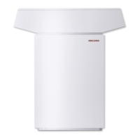
Connection WPL....A / AS and WPL....I
The terminals are located inside the WPL
control panel (Fig. 9 and 10) and become
accessible by removing the front panel.
During the installation, the control panel can
be withdrawn from the casing towards the
front. To terminate the cables, pivot the control
panel lid open after removing the screws fitted
to the top and side.
That makes all connecting terminals
accessible. For connection, see Fig. 12 and 13.
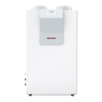
Connection WPL....IK / IKS
The terminals are located inside the WPL
control panel (Fig. 13) and become accessible
by opening the upper front panel.
2x
To terminate the cables, pivot the control
panel lid open after removing the screws fitted
to the top and l.h. side.
That makes all connecting terminals
accessible. For connection, see Fig. 12 and 14.
The IWS (abbreviation for integrated heat
pump control) is a PCB fitted as standard into
the heat pump control panel. The IWS controls
the contactors of the compressors and the
starting current limiter, receives the signal
inputs for high pressure, low pressure and
central faults and contains the BUS interface to
the WPM II.
WPM II
Observe the operating instructions
for the heat pump manager WPM II.
Connect the circulation pump for the heat
utilisation side in accordance with the
electrical connection diagram (Fig. 15) or the
design documentation.
Stand alone operation
In emergencies, this heat pump can also
operate without the heat pump manager (see
page 23).
However, under such circumstances the system
is no longer protected against frost, and the
system may ice up.
For external installation
Use only cables suitable for outdoor use to
VDE 0100 [or local regulations].
Route such cables through a conduit
(protective pipe); entry into the heat pump
can be arranged from below (Fig. 9).
Route the electrical cables inside the
heat pump in the cable trunking pro-
vided (Fig. 9, item 5).
For internal installation
Route the cables from the top through the
cable entries (Fig. 10 and 11).
Cut out the entries according to the cable Ø.
After connecting all cables, refit and seal the
cover over the mains terminal (X3) (Fig. 12).
Terminal ratings of the electric booster heater
Mark the box in front to the terminal ratings
on the relevant label below the type plate.
26_03_01_0297
WPL....A / I / IK W....AS / IKS
Power supply cable (compressor): 5x1.5 mm
2
3x2.5 mm
2
Power supply cable (DHC): 5x2.5 mm
2
5x4 mm
2
Control cable WPL 10 I / A (Mains): 3x1.5 mm
2
Control cable WPL 10 IK (Mains): 5x1.5 mm
2
BUS cable: J-Y (St) 2x2x0.8 mm
2
Flow sensor lead: 3x1.5 mm
2
Use appropriate cables in accordance with local regulations for all connections.
Check the strain relief function.

 Loading...


