16 | WPL 10 www.stiebel-eltron.com
INSTALLATION
Commissioning
26_03_01_1450
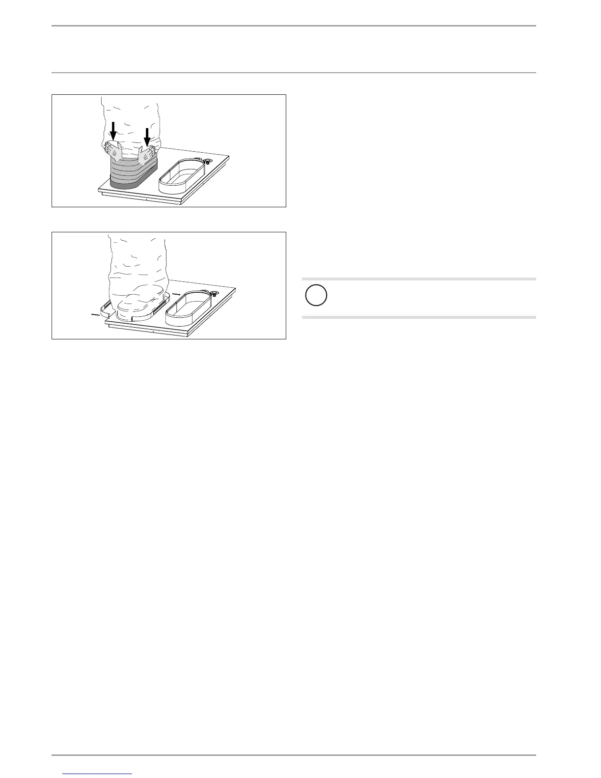
Pull the outer hose over the connector.
26_03_01_1452
Secure the hose using the oval hose clip provided and seal it.
Insulating the brickwork
Ensure that no cold bridges form between the brickwork and the
hose connection panels or wall outlets. Cold bridges can result in
condensation forming in the brickwork.
If necessary, fit suitable insulation between the brickwork
and the hose connection panels or wall outlets.
13.2 WPL 10 IK 3
Secure the fully assembled air hoses with the wing nuts (M5)
included in the pack to the heat pump (see Fig. "Dimensions
and connections WPL10IK3").
Use rawl plugs and screws suitable for the wall structure to attach
the wall connecting plates.
14. Commissioning
A qualified contractor must commission the appliance, make all
settings at the commissioning level of the heat pump manager,
and instruct the user.
Commission in accordance with these installation instructions
and the operating and installation instructions of the heat pump
manager. Our customer support can assist with commissioning,
which is a chargeable service.
Where this appliance is intended for commercial use, the rules of
the relevant Health & Safety at Work Act may be applied during
commissioning. For further details, check with your local super-
visory body; in Germany for example, this is theTÜV.
14.1 Checks before commissioning the heat pump
manager
!
Damage to the appliance and environment pollution
Observe the maximum system temperature in underfloor
heating systems.
Check whether the heating system is charged to the correct
pressure and whether the quick-action air vent valve in the
heat pump is open.
Check whether the outside temperature sensor and the re-
turn sensor are correctly placed and connected.
Check whether further sensors are correctly positioned and
connected.
Check whether the power supply is connected correctly.
14.2 Commissioning the heat pump manager
Commission the heat pump manager and make all settings in
accordance with the operating and installation instructions of the
heat pump manager.
14.3 Initial start-up
14.3.1 DIP switch (WP-Typ) on the IWS
(integral heat pump control unit)
Open the control panel.
The IWS is located on the r.h. side.

 Loading...


