22 | WPL 10 www.stiebel-eltron.com
INSTALLATION
Specication
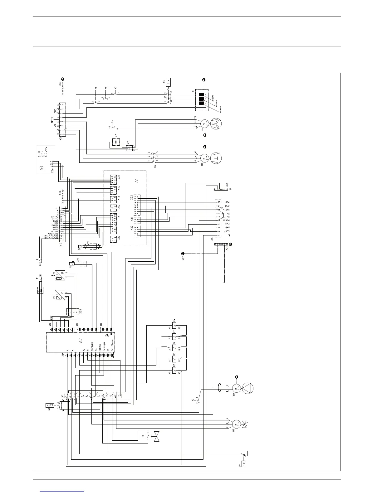
19.4 Wiring diagram WPL10IK3
25_03_01_0016
A1 WPM 2 heat pump manager
A2 Integral heat pump control unit IWS
B1 Temperature sensor, heat pump flow
B2 Temperature sensor, heat pump return
B5 Hot gas temperature sensor
E1 Instantaneous water heater (DHC)
F2 High pressure switch
F5 High limit safety cut-out for DHC
F13 Frost protection temperature sensor
H1 Heat pump ON indicator (green)
H2 Defrost ON indicator (blue)
K2 Compressor contactor
K4 Contactor fan
K5 Booster heater relay
K6 Booster heater relay
K7 Booster heater relay
M1 Compressor motor
M2 Pump motor
M3 Motorised diverter valve
M6 Fan motor
N2 Defrost pressure differential switch
P1 High pressure sensor
P3 Low pressure sensor
X1 Terminals
X2 LV terminal
X3 Power supply
X4 Control terminals
X23 Earth block, power supply
X26 LV earth block
X27 Earth plug-in block
X28 Socket terminal strip
X29 Socket plug IWS 12-PIN
X30 Socket plug IWS 3-PIN
X31 Socket plug IWS 5-PIN
Y1 Diverter valve - defrost
Z2 Fan capacitor

 Loading...


