56
ENGLISH
EN
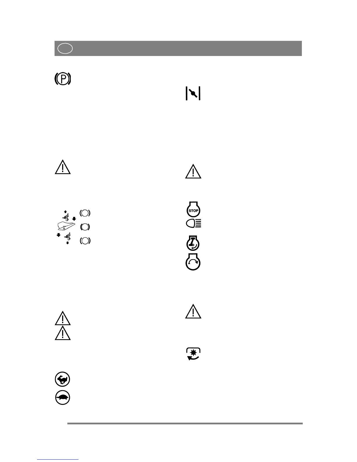
2.4.3 Inhibitor, parking brake (3:A)
The inhibitor locks the “clutch-brake”
pedal in the depressed position. This func-
tion is used to lock the machine on slopes,
during transport, etc., when the engine is
not running.
Locking:
1. Depress the pedal (3:B) fully.
2. Move the inhibitor (3:A) to the right.
3. Release the pedal (3:B).
4. Release the inhibitor (3:A).
Unlocking:
Press and release the pedal (3:B).
2.4.4 Driving-service brake (3:F)
If the machine does not brake as expect-
ed when the pedal is released, the left
pedal (3:B) should be used as an emer-
gency brake.
The pedal (3:F) determines the gearing ratio be-
tween the engine and the drive wheels (= the
speed). When the pedal is released, the service
brake is activated.
1. Press the pedal forward –
the machine moves forward.
2. No load on the pedal – the ma-
chine is stationary.
3. Press the pedal backward –
the machine reverses.
4. Reduce the pressure on the
pedal – the machine brakes.
There is an adjustment plate on the upper section
of the pedal. The adjustment plate can be adjusted
to three (3) positions to suit the driver’s foot.
2.4.5 Steering wheel (3:D)
The height of the steering wheel is infinitely ad-
justable. Undo the adjustment knob (3:E) on the
steering column and raise or lower the steering
wheel to the desired position. Tighten.
Do not adjust the steering wheel during
operation.
Never turn the steering wheel when the
machine is stationary with a lowered
implement. There is a risk of abnormal
loads on the servo and steering mecha-
nisms.
2.4.6 Throttle control (4, 5:G)
Control for setting the engine’s revs.
1. Full throttle – when the machine is in
operation, full throttle should always be
used.
2. Idling.
2.4.7 Choke control (4, 5:H)
A pull-type control to choke the engine when start-
ing from cold.
1. Control fully pulled out – choke valve
in carburettor closed. For starting cold en-
gine.
2. Control pushed in – choke valve open.
For starting warm engine and when oper-
ating the machine.
Never operate the machine with the choke
pulled out when the engine is warm.
2.4.8 Ignition lock/headlight (4, 5:I)
The ignition lock is used for starting and stopping
the engine. The ignition lock is also the switch for
the headlight.
Do not leave the machine with the key
in position 2 or 3. There is a fire risk,
fuel can run into the engine through the
carburettor, and there is a risk of the
battery being discharged and damaged.
Four positions:
1. Stop position – the engine is short-
circuited. The key can be removed.
2. Operating position – headlight activat-
ed.
3. Operating position – headlight not acti-
vated.
4. Start position – the electric start motor
is activated when the key is turned to the
spring-loaded start position. Once the en-
gine has started, let the key return to oper-
ating position 3.
Turn the key to position 2 to light the
headlight.
2.4.9 Power take-off (4, 5:K)
The power take-off must never be en-
gaged when the front-mounted imple-
ment is in transport position. This will
destroy the belt transmission.
Switch for engaging/disengaging the electromag-
netic power take-off for operating front-mounted
accessories. Two positions:
1. Press the front part of the switch – the
power take-off is engaged. The symbol
will light up.
2. Press the rear part of the switch – the
power take-off is disengaged.
2.4.10 Hour meter (2:P)
Indicates the number of working hours. Only
works when the engine is running.


 To Next Page