125FS 240 C, FS 260 C, FS 360 C, FS 410 C, FS 460 C-M
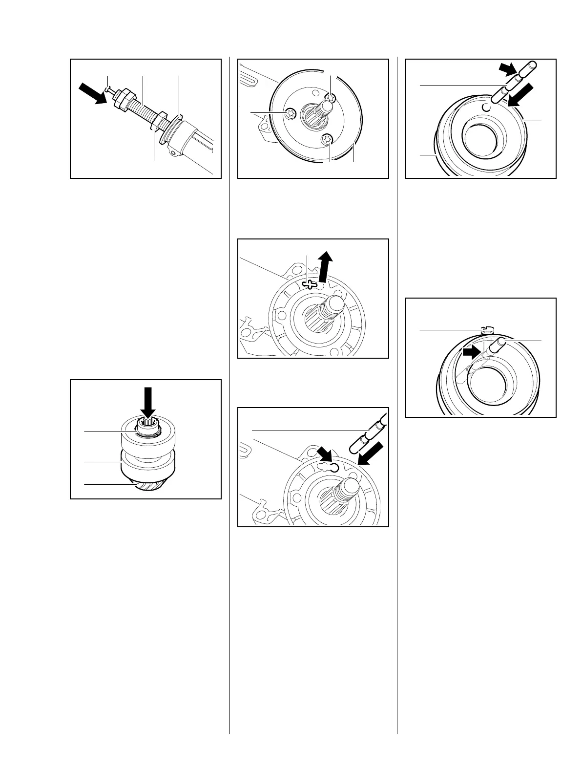
: Push the punch (1) into puller (2)
5910 890 4408 as far as it will go
– Insert is spread behind the
drive pinion
: Position washer (4) on the gear
housing, hold locknuts in place
and twist nut (3) until the drive
pinion set is pulled out of the
bearing seats
– Pull out the punch and remove
the drive pinion set from the
puller
Always use new ball bearings.
: Remove the circlip (1)
: Position set of pinions on the
outer race of the ball bearing (2)
and use a suitable tool to press
out the drive pinion (3)
3
5904RA539 TG
1 2 4
5404RA519 TG
1
2
3
: Unscrew screws (1) and remove
guard ring (2)
: Pry out the guard plugs (1)
The locking pin (1) of puller
5910 890 4407 must engage the
hole (arrow) – puller is secured
against twisting with the locking pin.
1
5904RA520 TG
1
1
2
5904RA521 TG
1
5904RA544 TG
1
: Orient the ring (1) of puller
5910 890 4407 so that the
narrow collar (2) faces away from
the gearbox
: Push locking pin (3) into the hole
as far as the indentation (arrow)
: Screw in the clamping screw (1)
until it rests against the
indentation (arrow) of the locking
pin (2)
: Tighten clamping screw (1)
5904RA545 TG
3
2
1
5904RA546 TG
1
2
 Loading...