48 MS 171, MS 181, MS 211
– Install the switch shaft, b 12.1
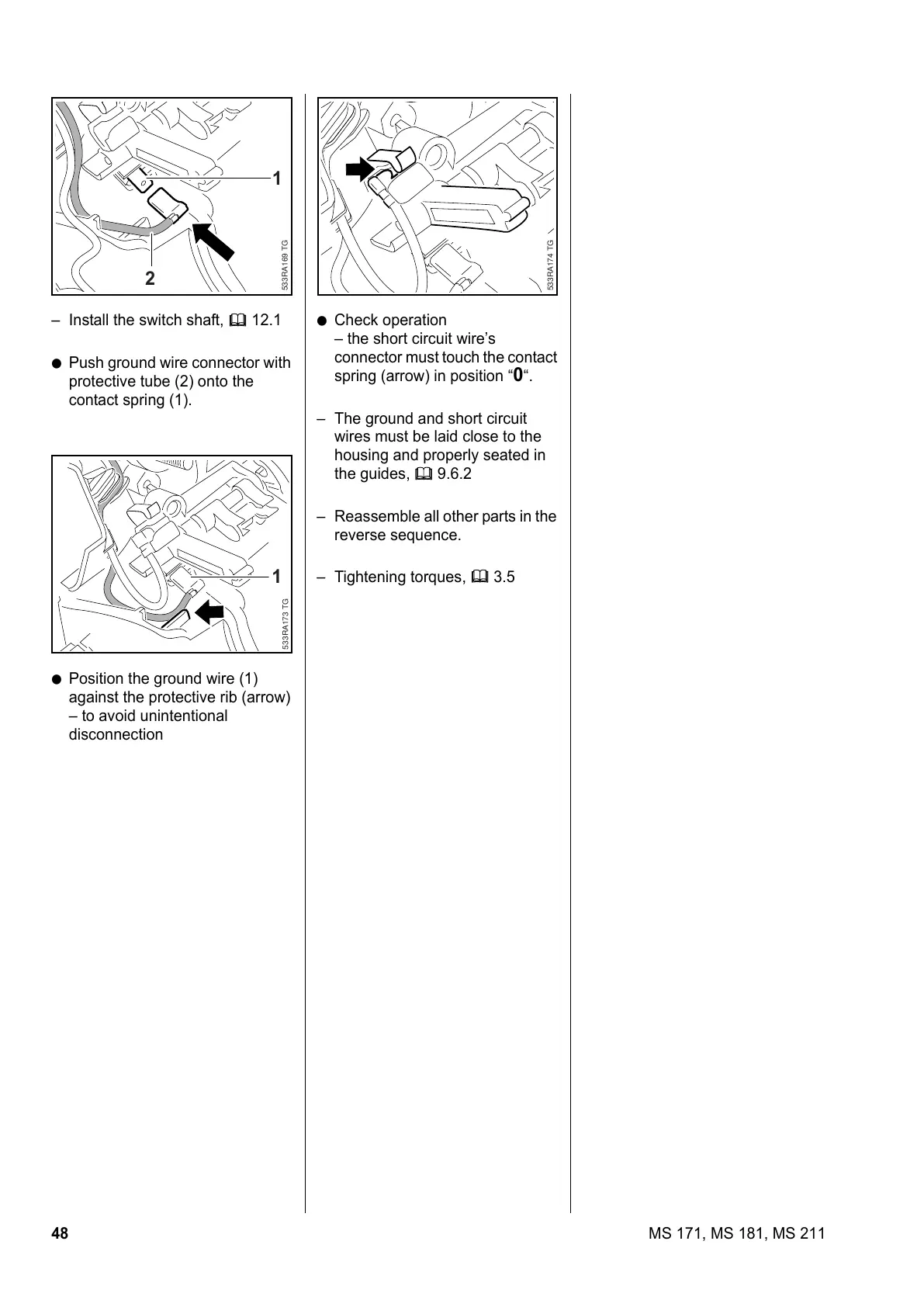
: Push ground wire connector with
protective tube (2) onto the
contact spring (1).
: Position the ground wire (1)
against the protective rib (arrow)
– to avoid unintentional
disconnection
533RA169 TG
1
2
533RA173 TG
1
: Check operation
– the short circuit wire’s
connector must touch the contact
spring (arrow) in position “
0“.
– The ground and short circuit
wires must be laid close to the
housing and properly seated in
the guides, b 9.6.2
– Reassemble all other parts in the
reverse sequence.
– Tightening torques, b 3.5
533RA174 TG