64 MS 171, MS 181, MS 211
12. Master Control Lever
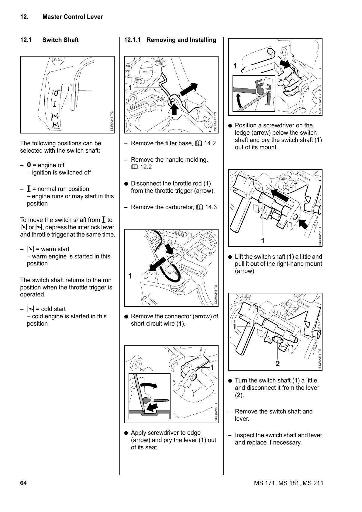
12.1 Switch Shaft
The following positions can be
selected with the switch shaft:
–
0 = engine off
– ignition is switched off
– # = normal run position
– engine runs or may start in this
position
To move the switch shaft from # to
k or l, depress the interlock lever
and throttle trigger at the same time.
– k = warm start
– warm engine is started in this
position
The switch shaft returns to the run
position when the throttle trigger is
operated.
– l = cold start
– cold engine is started in this
position
533RA246 TG
12.1.1 Removing and Installing
– Remove the filter base, b 14.2
– Remove the handle molding,
b 12.2
: Disconnect the throttle rod (1)
from the throttle trigger (arrow).
– Remove the carburetor, b 14.3
: Remove the connector (arrow) of
short circuit wire (1).
: Apply screwdriver to edge
(arrow) and pry the lever (1) out
of its seat.
533RA247 TG
1
533RA248 TG
1
533RA249 TG
1
: Position a screwdriver on the
ledge (arrow) below the switch
shaft and pry the switch shaft (1)
out of its mount.
: Lift the switch shaft (1) a little and
pull it out of the right-hand mount
(arrow).
: Turn the switch shaft (1) a little
and disconnect it from the lever
(2).
– Remove the switch shaft and
lever.
– Inspect the switch shaft and lever
and replace if necessary.
533RA252 TG
1
533RA255 TG
1
533RA251 TG
2
1