4
D
S Reduzierstück von innen aus
dem Brühebehälter heraus-
drücken und mit dem
Anschlussstutzen voran von
innen wieder in den Brühebe-
hälter stecken und einrasten.
Der Anschlussstutzen ragt nun
nach unten aus dem
Brühebehälter heraus.
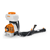
S Kupplungsstück (19) auf die
Sechskantmutter des Geblä-
serades (20) stecken.
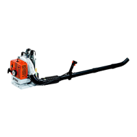
S Druckpumpe mit den vier
Schrauben 4x20 so montie-
ren, dass die Seite mit zwei
Anschlussstutzen (mit einem
aufgesteckten Schlauch) zur
Austrittsöffnung des Geblä-
ses weist.
S Stutzen am Gebläsegehäuse
mit der Kappe (21) versch-
ließen.
S Schelle (22) auf den
Schlauch (17) schieben.
Schlauch auf den freien Stut-
zen an der Druckpumpe
stecken und mit Schelle
sichern.
Hinweis: Die an der Pumpe
angeschlossenen Schläuche
haben folgende Funktionen:
Saugschlauch (17) Rücklauf
(23) und Vorlauf (24).
S Motoreinheit und Rücken-
polster wieder an der Rück-
enplatte montieren.
Bei neuen Geräten:
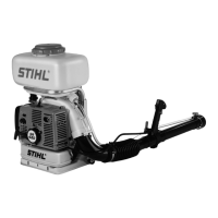
S Kraftstoffschlauch am Verga-
ser aufstecken. Falls vorhan-
den Schlauch an der
Tanklüftung aufstecken.
S Abdeckhaube montieren.
S Anwerfvorrichtung montie-
ren.
S Überwurfmutter (25) lösen.
Reduzierstück (5) vom
Brühebehälter abnehmen.
G
S Push the reducer out of the
container (from inside). Turn
the reducer round and push it
back into the container (from
inside) so that it snaps into
position.
The connecting stub now
projects from the bottom of the
container.
S Fit the coupling element (19)
on the fanwheel’s (20) hexa-
gon nut.
S Use the four 4 x 20 screws to
mount the pressure pump so
that its two stubs (with one
hose fitted) face the fan out-
let.
S Use the cap (21) to seal the
stub on the fan housing.
S Slide the clip (22) over the
hose (17). Connect the hose
to the other stub on the pres-
sure pump and secure it with
the clip.
Note: The functions of the
hoses connected to the pump
are as follows: Intake hose (17),
return hose (23) and feed hose
(24).
S Reassemble the powerhead
and back pad on the back-
plate.
On new machines:
S Push the fuel hose onto the
carburetor. Push the hose (if
fitted on your machine) onto
the tank vent.
S Fit the shroud.
S Mount the rewind starter.
S Loosen and remove the
union nut (25). Remove the
reducer (5) from the contai-
ner.
F
S Chasser le raccord réducteur
du réservoir de liquide,
depuis l'intérieur, et le
remettre dans le réservoir de
liquide, par l'intérieur, avec
l'embout en premier ; le faire
encliqueter.
L'embout dépasse alors en bas
du réservoir de liquide.
S Emboîter l'élément
d'accouplement (19) sur
l'écrou à six pans de la tur-
bine (20).
S Fixer la pompe refoulante au
moyen des quatre vis 4x20
de telle sorte que les deux
raccords (avec un tuyau
branché) soient orientés vers
l'ouverture de sortie de la tur-
bine.
S Fermer le raccord du carter
de turbine au moyen du
capuchon (21).
S Glisser le collier de serrage
(22) sur le tuyau (17). Glisser
le tuyau sur le raccord libre
de la pompe refoulante et le
serrer avec le collier de
serrage.
Remarque: Sur la pompe sont
branchés les tuyaux d'aspiration
(17), de retour (23) et d'aller
(24).
S Remonter le groupe moteur
et le rembourrage sur la pla-
que dorsale.
Sur les nouveaux appareils :
S Brancher le tuyau à carburant
sur le carburateur. Le cas
échéant, brancher le tuyau
sur le dispositif d’aération du
réservoir de carburant.
S Monter le capot.
S Monter le dispositif de lance-
ment.
S Desserrer l'écrou-chapeau
(25). Enlever le raccord
réducteur (5) du réservoir de
liquide.
372BB005 KN
19 20
22
372BB006 KN
17
21
23
24
25
5
372BB007 KN
 Loading...