Parameter description:
P1: Setpoint / DeltaW for control circuit 2
Adjusting the setpoint of control circuit 2.
If A5=1, the setpoints for control circuit 1 and 2 are linked with one another via switching difference
DeltaW, which can be adjusted with P1. (operation with DeltaW)
The following applies: setpoint thermostat 2 = setpoint control circuit 1 + delta W2.
This difference can take positive or negative values. Thus, a leading or following contact can be
realised.
P2: Hysteresis contact K1
P3: Hysteresis contact K2
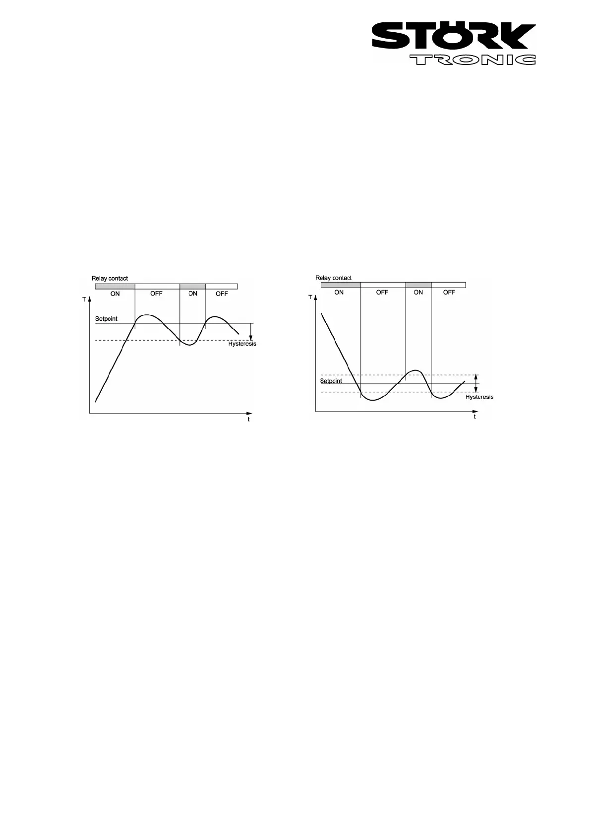
The hysteresis can be set symmetrically or one-sided at the setpoint (see A40, A41).
At one-sided setting, the hysteresis works downward with heating contact and upward with cooling
contact. At symmetrical hysteresis, half of the hysteresis’ value is effective below and half of the
value above the switching point (see fig. 1 and 2).
Fig. 1: Heating controller, Fig. 2: Cooling controller,
one-sided hysteresis symmetrical hysteresis
The hysteresis is only effective with thermostatic control, if PID mode is activated the hysteresis
becomes ineffective.
P4: Control range limitation – minimum value
P5: Control range limitation – maximum value
The adjustment range of the setpoint can be limited in both directions. This is to prevent the end
user of a unit from setting inadmissible or dangerous setpoints.
Parameters P7…P10 are only available if either K1 or K2 operates in PID mode
(A6 = 1 or A7 = 1)
P7: Proportional band at PID regulation
The proportional part works in such a way that with approximation of the actual value to the
setpoint the variable is reduced linearly from +-100% to 0%.
P8: Reset time Tn, I-factor
P9: Lead time Tv, D-factor
These settings determine the intensity and effect of the I- and D-portion. If "0" is set, then the
portion is inactive.
P10: Cycle time Tp
The cycle time is the time, in which the control output runs through one switching period, i.e. once
switched out and once switched on. The smaller the cycle time, the faster the regulation. By
consequence, however, there is also an increased switching frequency of the exit, which can lead
 Loading...