CD80/CD80AE Processor Retrofit Kit Installation 7
CD80/CD80AE Processor Retrofit Kit
Installation Guide
c. Attach the new temperature sensor PCB to the old temp sensor bracket using cable tie wraps (note, cable
tie wraps are not supp
lied with kits).
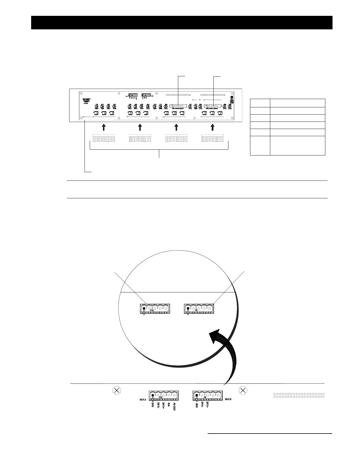
Step 7. Connect J1-J4 connections (from original rack wiring) to the bottom of processor interface card as shown in
Figure 4.
Figure 4: Control Cable Connections (J1 through J4)
Step 8. If applicable...if a DMX input cable was connected to original interconnection board (in upper left side of
CD80/CD80AE dimming rack), move this cable to rear of retrofit kit processor housing. As illustrated in
Figure 5, connect DMX input cable to either Mux A or Mux B five pin connector.
Figure 5: Retrofit Processor - DMX Connections (if applicable)
J4 Connection J3 Connection J2 Connection J1 Connection
Back of Retrofit Processor
Control Communication Cables
Note: *Connections P21, P22 and J5 are only used when the upper connector interconnect PCB is being re-used,
otherwise these connections will not be used with retrofit kit processor.
Control Communication Cables
Conn Module Rows
J1 1 & 2
J2 3 & 4
J3 5 & 6
J4 7 & 8
J5
AMX Only (not for
DMX and not used on
CD80AE)
P21*
(from CD80/CD80AEAE Dimming Rack)
J5*
P22*
MUX A
GND
DATA -
DATA +
ANA
AN GND
GND
DATA -
DATA +
MUX B
Back of Retrofit Processor
Mux A Connector*
Mux B Connector*
*For DMX connections, if applicable.