Operations Model 6DS-SP Planarizer
3 - 92 Version 4.0 - February 1998
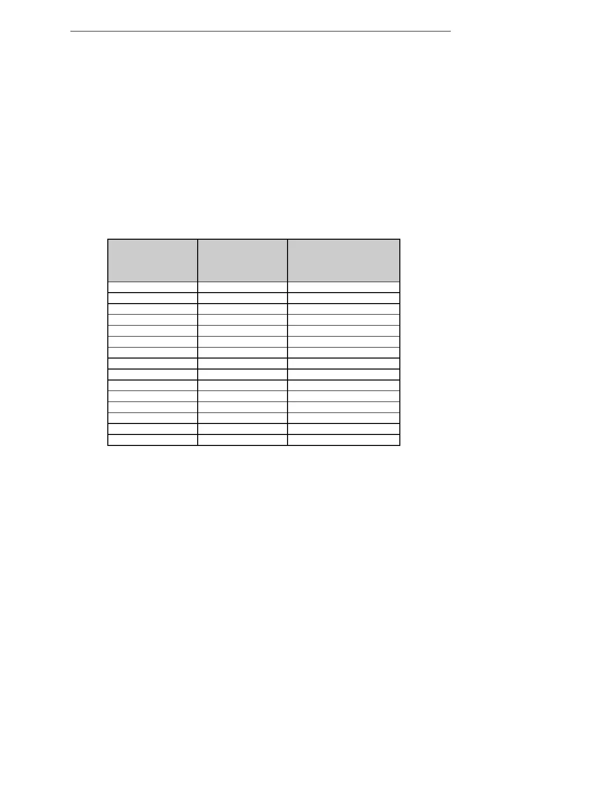
CYLINDER PRESSURE / PAD FORCE TABLE
The table below displays approximate pad forces for corresponding cylinder
gauge pressure values. To achieve a specified pad force, following the
procedure detailed in this section, set the cleaning station cylinder pressure
at the associated value.
Note: The table below includes an offset to compensate for the moving
weight.
Cylinder Pressure
(psi)
Pad Force
(lbs)
Pad psi
(lbs-in*2)
20 2.0 0.12
25 6.4 0.40
30 10.8 0.68
35 15.3 0.96
40 19.7 1.24
45 24.1 1.52
50 28.6 1.80
55 33.0 2.08
60 37.4 2.35
65 41.9 2.63
70 46.3 2.91
75 50.7 3.19
80 55.2 3.47
85 59.6 3.75
90 64.0 4.03
Left Cleaning Pad Pressure
Valve Location:
on valve panel located inside Left Front
Service Door
Label Number/Name: Solenoid 2
Right Cleaning Pad Pressure
Valve Location:
on valve panel located inside Left Front
Service Door
Label Number/Name: Solenoid 3
Control: valve regulator, gauge
Setting: As desired, per table above.