Strasbaugh Installation
Version 4.0 - February 1998; Update 11/06/01 2 - 17 U
VACUUM SEPARATOR
Related Engineering Drawings
• 219771A1
Vacuum System Assembly
• 277180P1
Vacuum System Diagram
EXHAUST
The machine exhaust duct (5) connection is to a vacuum source rated at
approximately 250 SCFM. A six-inch duct or hose is required to connect to the
exhaust duct.
EXHAUST FAILURE INDICATOR
The 6DS-SP offers a system to relay a signal from the machine operator’s facility
exhaust failure monitoring system to the local 6DS-SP machine operator. The
system requires the user to supply a safety-rated normally-open contact or
switch. Closing of that contact, if connected to the 6DS-SP machine, will
"announce" an exhaust failure by turning on a set of red lamps, sounding
intermittent 85 dB audible alarms, and displaying an alarm message on the
screen. If the GEM option is installed, the machine will also communicate the
exhaust failure to the host computer.
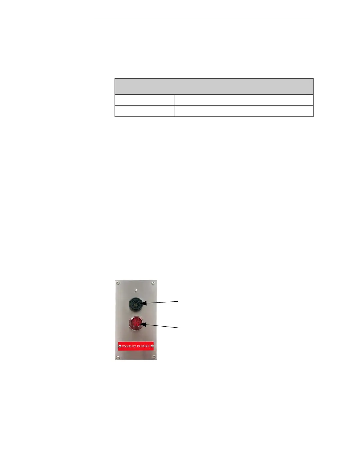
Figure 2-3 Exhaust Failure Alarm Panel
The red LED light and audible alarm panels are located in the following
locations:
• Above Elevator Doors (left side of machine)
• Above Front Polish Doors (front of machine)
Audible Alarm
Red Lamp
 Loading...