Strasbaugh Mechanical Maintenance Procedures
Version 4.0 - February 1998 9 - 31
12
3
6
9
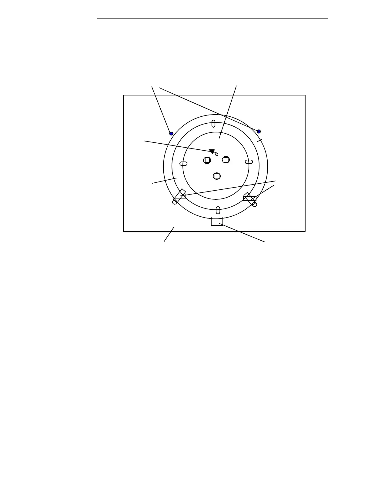
locator pins
pivoting
retainers
wafer manifold plate
inner
gimble ring
outer gimble ring
carrier maintenance fixture
locking block
swivel
elbow barb
Figure 9-11 Orientation of Gimbal Ring/Manifold Plate Unit on the Bench Top
Carrier Fixture
3. Using the locking block and screw, secure the gimbal ring/manifold
plate assembly to the bench top carrier fixture.
4. Manually install the two pivoting ring retainers into the two 8-32 holes
located approximately at 4 o’clock and 8 o’clock.
Note: When installed, the pivoting retainers prevent the inner
gimbal ring and manifold assembly from rotating during
adjustments.