Do you have a question about the Strebel S-CB+ Series and is the answer not in the manual?
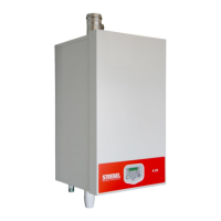
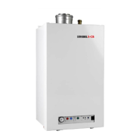
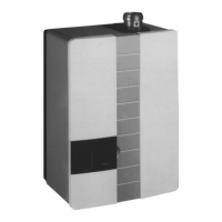
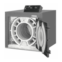
Overview of the S-CB+ boilers' high efficiency and performance characteristics.
Detailed technical specifications including dimensions, heating values, and gas consumption.
Dimensional drawings and connection sizes for S-CB+ models 60 to 120.
Dimensional drawings and connection sizes for S-CB+ models 150 to 180.
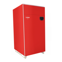
List of optional accessories available for the S-CB+ boilers.
Instructions on how to unpack the boiler and check its contents.
General guidelines and requirements for boiler installation location and environment.
Step-by-step instructions for securely mounting the boiler on the wall.
Identification of water and gas connection points on the boiler.
Details on connecting the condensate drain and siphon.
Guidance on connecting flow and return pipes, including valve placement.
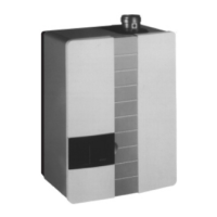
Recommendations for selecting and installing an expansion vessel.
Requirements for installing a pressure relief valve.
Information on system bypass requirements and frost protection.
Explanation of pump control and delta T monitoring.
Description of the built-in frost protection feature and its limitations.
Importance and method of installing strainers and dirt separators.
Guidelines for water quality parameters like pH and hardness.
Precautions when using plastic pipes, recommending plate heat exchangers.
Function of the automatic air vent and de-aeration program.
Precautions for automatic water refill systems and leak detection.
Requirements and monitoring of water pressure within the boiler.
Compatibility of chemical treatments with boiler components.
Installation requirements for underfloor heating systems.
Procedure for flushing the system before installation.
Examples of typical heating circuit installations.
Graphical representation of pump performance curves for different models.
Information on the maximum electrical power consumption of the pumps.
Overview of the positive pressure flue system and pressure drop limits.
Requirements for air supply ducts, quality, and installation in humid areas.
Guidelines for selecting and installing flue terminals and common duct systems.
Specifics for the twin pipe version of the S-CB+ 60 boiler.
Regulations for positioning air inlets and flue outlets on flat roofs.
Minimum requirements for flue gas material for Eco Boilers (B23P).
Requirements for C63 certified boilers and flue gas materials.
Table of resistance values for various flue gas and air supply configurations.
Examples of typical flue gas and air supply system configurations.
General safety and wiring precautions for electrical installation.
Diagram showing the terminal connections for various boiler functions.
Detailed explanation of each electrical connection terminal and its function.
Detailed electrical schematic diagrams for the boiler.
Table listing sensor types and their corresponding resistance values.
Description of the control panel buttons, display, and indicators.
Overview of the boiler's control panel menu hierarchy.
Procedure for confirming or canceling changes made to settings.
Function to lock the user interface to prevent accidental changes.
Access to maintenance-related settings and reminders.
Allows adjustment of heating and hot water set points.
Access to various boiler parameters for advanced configuration.
Explanation of lock-out codes and their causes.
General functions of the boiler and their possible uses.
Settings for optimizing burner start behaviour.
Configuration for pumps with Electronic Commutation technology.
Factory settings for central heating control behavior.
Connecting and using an ON/OFF room thermostat.
Connecting an OpenTherm controller for temperature reading and programming.
Calculating flow temperature based on outdoor temperature.
Controlling flow temperature using an external 0-10 Vdc signal.
Controlling burner input using an external 0-10 Vdc signal.
Activating timer function for external night reduction.
Control of DHW pump or 3-way valve for indirect water tanks.
Connecting an external thermostat for tank temperature control.
Connecting a tank sensor for hot water set point and control.
Setting parameters for cascaded boilers and their connections.
Obtaining information about cascade operation.
Managing output and sequence of boilers in a cascade.
Procedure for flushing the boiler and heating installation.
Steps for filling and venting the boiler and heating system.
Procedure to verify water flow and pump operation.
General checks before starting the boiler, including gas pressure.
Instructions for the initial operation and burner adjustment.
Situations requiring burner adjustment and overview of procedures.
Tables providing CO2 and O2 values for burner adjustment.
Diagrams showing gas valve setting screws for different boiler models.
Distinguishing between A+C and B+J gas valve classes.
General scheme for carrying out burner adjustment procedures.
General remarks on CO2 deviations and adjustment tolerances.
Procedure for adjusting the burner at maximum load.
Procedure for adjusting the burner at minimum load.
General remarks for case B, distinguishing single and double valve boilers.
Adjusting single valve boilers at maximum load.
Adjusting single valve boilers at minimum load.
Adjusting double valve boilers at maximum load.
Adjusting double valve boilers at minimum load.
Detailed procedure for adjusting the burner at maximum load.
Detailed procedure for adjusting the burner at minimum load.
Procedure for putting the boiler in standby mode.
Procedure for completely powering off the boiler.
List and explanation of fault codes and their corrective actions.
Explanation of lock-out codes and how to reset the boiler.
Recommendations for regular boiler maintenance and service.
Detailed procedures for boiler inspection and maintenance tasks.
Example schematic for System Type 1 installation.
Example schematic for System Type 2 installation.
Example schematic for System Type 3 installation.
Example schematic for System Type 4 installation.
Example schematic for System Type 5 installation.
Example schematic for System Type 6 installation.
Example schematic for System Type 7 installation.
Example schematic for System Type 8 installation.
Example schematic for System Type 9 installation.
Example schematic for System Type 11 installation.