Do you have a question about the Strebel S-HR 51 and is the answer not in the manual?
Lists all components included in the supply kit for the unit, ensuring readiness for use.
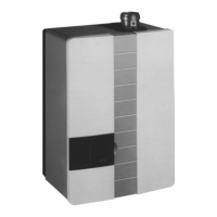
Details the requirements and procedures for physically attaching the unit to a wall, including space considerations.
Explains how to connect the unit to the central heating installation using compression fittings and pipe reducers.
Describes the provision and connection of expansion tanks for S-HR-T and other S-HR units, including pre-pressure guidelines.
Outlines requirements for underfloor heating systems, including pipe standards and potential separation needs.
Details the gas pipe connection, emphasizing the female thread and the need for correct installation by registered contractors.
Explains the connection of the hot water supply for S-HR-T models, including inlet combination and safety valve usage.
Specifies how to connect the condensation discharge pipe to the waste via an open connection, noting minimum diameter requirements.
Covers the installation of flue gas and air supply systems, including pipe diameters, lengths, and British Standards compliance.
Describes the functions of various keys on the control unit and how they interact with the display for operation and settings.
Guides through the process of filling and venting the central heating system, including pressure checks and the automatic venting program.
Details the procedure for venting the calorifier and hot water installation by opening a hot water tap until air is removed.
Explains how to initiate operation for central heating via the control unit and the burner start process.
Describes how the hot water program is activated when there is a heat requirement from the boiler.
Outlines how to make adjustments via the Control Tower, distinguishing between user and installer levels and accessing parameter chapters.
Details how to measure maximum air displacement to check for contamination during operation and subsequent servicing.
Explains how to check the factory-set zero pressure control by monitoring fan operation and pressure differences.
Describes how to check the factory-set CO2 percentage and adjust it using the adjustment screw on the gas block.
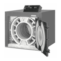
Provides step-by-step instructions for cleaning various components like the air unit, burner bricks, heat exchanger, and waste trap.
Covers additional checks such as ionisation current, visual inspection of components, and leak checks for safety valves.
Advises on the recommended frequency for unit inspections (every two years) and overhauls (every four years).
Illustrates a typical connection diagram for a radiator installation that does not use thermostat valves.
Shows a connection diagram for a radiator system equipped with thermostat valves and a by-pass.
Presents a diagram for connecting the unit to a radiator zone and an underfloor heating zone, including controllers.
Displays a connection diagram for a radiator setup and a separately controlled underfloor heating zone.
Provides a connection diagram for a system with two independently controlled radiator zones, detailing group controllers and pumps.