8
System Overview
The Stryker CORE Powered Instrument Driver (console) provides an integrated, centrally controlled environment that promotes safe
and economical surgical practice.
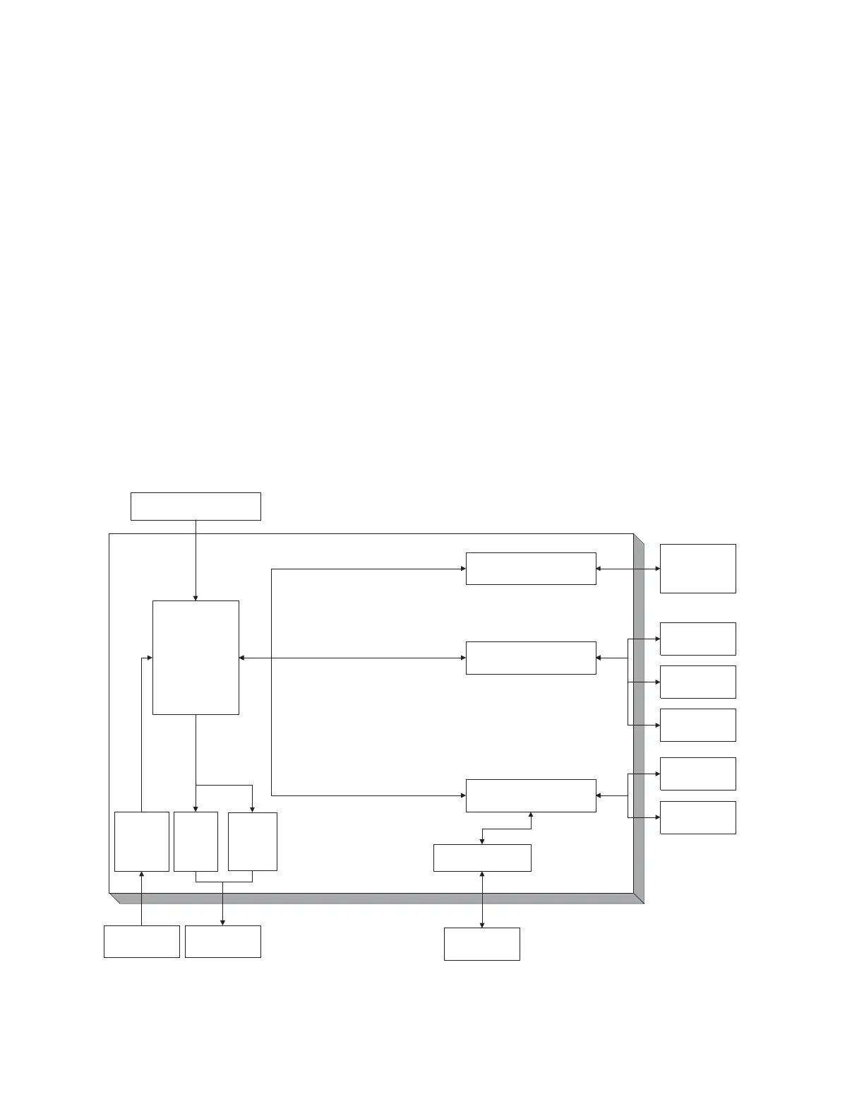
The console’s software provides control over system components including the console, the graphical user interface (GUI), the
irrigation pump, and the connected handpieces and footswitches (see figure 1). The software’s file management capability allows you
to save and store user preference settings and have convenient access to a favorites list of the most frequently used files to improve
efficiency.
The color display, with its touch sensitive screen, provides an intuitive graphical user interface that allows you to view multiple system
components and set their parameters with the touch of a finger. Changes may be made rapidly, with little to no interruption during
surgery.
Multiple handpieces and footswitches may be connected and operated simultaneously from a single console. Because options vary
among different handpieces, the console will only display those options that are related to the connected handpiece.
An integral irrigation pump system reliably supplies coolant/irrigation to the cutting site with adjustable flow rates.
Various cutting accessories and irrigation cassettes used with the system are also recognized and identified on the console screen by
means of a wireless tag technology.
Console settings, like display brightness and speaker volume, may be easily adjusted. The on board speaker provides audible
feedback during operation and configuration.
The console accepts either 115 VAC or 230 VAC input and has the capability to power heavy-duty handpieces.
The Stryker Firewire Backbone (SFB) serial connection provides a serial communications channel between the console and other
devices. This feature allows software upgrades over a computer network.
C
O
R
E
C
on
s
ol
e
Main Processor
SFB Serial Connection
Handpiece Control
Footswitch and Irrigation
Pump Control
Speaker
Touch
Sensitive
Screen
Handpiece 1
Handpiece 2
Handpiece 3
Footswitch 1
Footswitch 2
Color
Display
Irrigation Pump
Other Devices
via Computer
Network
Facility Power
Finger/Stylus
Input
Graphical/
Audio Output
Irrigation Pump
Cassette
Figure 1. System Block Diagram
 Loading...