NNoottee -- If you have a previously installed floor plate without the anchor-to-vehicle cable, measure either 3 in. or 7 in.
toward the head end from the locator position A (Figure 7). Mark the location in the middle of the channel. This will be
your electrical inlet location. See Installing the floor plate (6390-009-020) for instructions about how to connect the
electrical.
FFiigguurree 77 –– FFlloooorr ppllaattee llooccaattoorr ppoossiittiioonn -- ffoooott eenndd
NNoottee -- The safety hook (B) and extra mounting hole locations (C) are shown for reference only (Figure 7). They are not
used for PPeerrffoorrmmaannccee--LLOOAADD installation.
10.Place the connectors into the floor plate pocket.
11.Apply silicone sealant to the electrical rubber grommet to completely seal the electrical pass through.
WWAARRNNIINNGG -- Always seal all gaps to the exterior of the vehicle to prevent exhaust fumes from entering the vehicle
patient compartment.
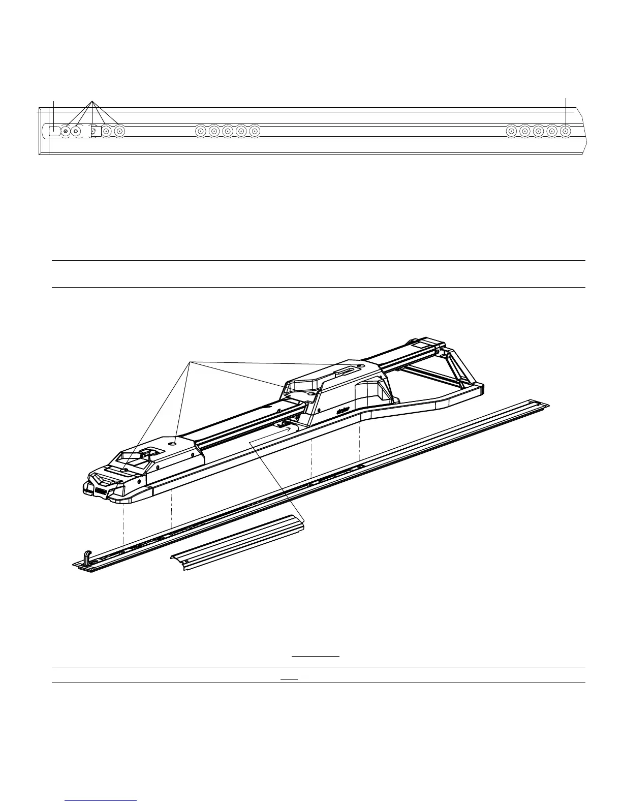
12.Rotate the spin caps (A) a half turn to access the attached floor plate bolts that are under the caps (Figure 8).
NNoottee -- Do not fully tighten the floor plate bolts until all four bolts are aligned and started.
FFiigguurree 88 –– AAttttaacchh tthhee ffaasstteenneerr
13.Using a 3/8” hex wrench, install the attached floor plate bolt that is closest to the head end.
14.Using a 3/8” hex wrench, install the other three attached floor plate bolts (A) into the two cleats (Figure 8).
15.Using a torque wrench, tighten each floor plate bolt to 60±10 ft-lb.
WWAARRNNIINNGG -- Always make sure that you tighten all four floor plate bolts to the recommended torque.
16.Close the spin caps.
17.Insert the un-notched side of the center cover assembly (6392-001-011) (B) into the opening in the head end housing
(Figure 8).
EN 22 6392-009-001 Rev D.3