Do you have a question about the Stryker TPS 5100-8 and is the answer not in the manual?
General safety and usage guidelines, including warnings and care recommendations for the TPS Footswitch.
Explains the symbols and factory default settings for the footswitch pedals and pads.
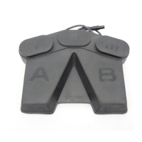
Details the factory default functions of the footswitch pedals (A and B) for speed and direction control.
Explains the factory default functions of the footswitch pads (I, II, and III) for irrigation, handpiece, and attachment selection.
Addresses issues where the footswitch is not recognized by the console display.
Covers problems with the footswitch failing to operate the connected handpiece.
Details the footswitch model number, electrical input/output, IPX7 rating, and dimensions.
The Stryker TPS Footswitch, model 5100-8, is a crucial component of the Total Performance System, designed to provide surgeons with sterile field control over TPS handpieces. This device eliminates the need for a circulating assistant to actuate the console, allowing the surgeon to select system functions directly from the sterile environment. The footswitch is compatible with both TPS and Endoscopy handpieces, featuring dual-function pads with unique functionalities tailored to the activated handpiece.
The TPS Footswitch operates through a combination of pedals and pads, each assigned specific functions that can be user-programmable when connected to TPS Consoles with version 3.0 software or higher.
Pedals (Factory Default Settings):
Pads (Factory Default Settings): The functionality of the pads adapts based on whether a TPS or Endoscopy handpiece is activated.
Tapping the pad enables handpiece irrigation for the activated TPS handpiece. Irrigation flows only while the handpiece is running. Tapping the pad again stops the flow.
Depressing the pad until the console beeps twice initiates immediate irrigation prior to handpiece operation, which then continues during handpiece operation. Tapping the pad again stops the flow.
*   **II (Center Pad):**
    *   **Handpiece (Endo/TPS):** Tapping this pad activates the desired handpiece.

*   **III (Right Pad):**
    *   **Attachment Select (TPS Handpieces):** This function scrolls through a list of attachments on the console screen. The surgeon stops scrolling when the correct attachment, assembled to the handpiece, is reached.
    *   **High/Low Speed (Endo Handpieces):** This function toggles control between the high and low speed settings selected on the console.
The TPS Footswitch is designed for intuitive and reliable operation within the surgical environment. Its robust construction ensures durability, while its ergonomic design facilitates comfortable and precise control during procedures. The dual-functionality of the pads, adapting to the type of handpiece in use, streamlines workflow and reduces the need for multiple control devices. The ability to program the footswitch when connected to compatible TPS Consoles offers customization, allowing surgeons to tailor the device's functions to their specific preferences and procedural requirements. This programmability enhances flexibility and efficiency in the operating room. The footswitch's integration with the Total Performance System ensures seamless communication and control, contributing to a more efficient and safer surgical experience.
Proper maintenance of the TPS Footswitch is essential for its longevity and reliable performance. Users are advised to file the important information provided in the manual in their maintenance records. Before each use, a thorough inspection for any signs of damage is critical. If any damage is apparent, the device should not be used. For detailed instructions on cleaning, maintenance, and sterilization, users should refer to the "TPS Cleaning, Maintenance, and Sterilization Recommendations" for instrument care information. In case of operational issues, a troubleshooting guide is provided to address common problems. For instance, if the footswitch is not indicated on the console display, users should ensure the cable connector is fully seated. If the footswitch does not operate the handpiece, verifying that the handpiece is properly plugged into the console and that its cable connector is fully seated is recommended. If the footswitch is damaged or requires repair, it should be returned to Stryker. For customers outside the USA, contact the nearest Stryker Subsidiary for repair and loaner program information. Adhering to these maintenance guidelines helps ensure the footswitch remains in optimal working condition, contributing to patient safety and surgical efficiency.
| input voltage | 5VDC |
|---|---|
| input current | 18mA |
| output voltage range | 2.5VDC to 4.9VDC |
| IP rating | IPX7 |
|---|
| width | 11.7 in [297 mm] |
|---|---|
| depth | 9.1 in [231 mm] |
| height | 1.9 in [48.2 mm] |
| weight | 5.6 lbs [2.6 kg] |
| cord length | 15 ft [457 cm] |