SECTION 1 - Engine Compartment
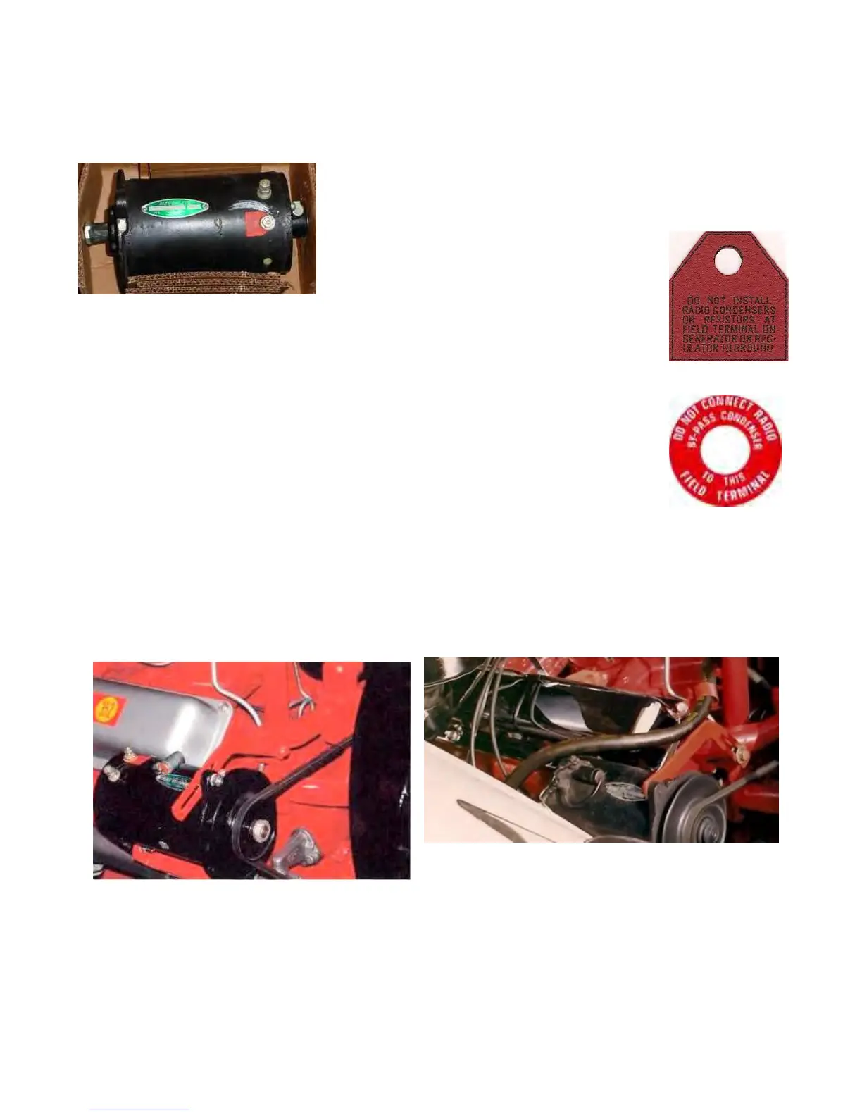
Generator
The generator should be painted black. The green & silver
AUTO-LITE name plate actually appears upside down when
viewed from the passenger fender side of the car.
There should be a small red tag on the field
terminal, the one which does not connect to
the radio condenser. The tag is about 1-1/4" x
1" and has black lettering on it which reads:
DO NOT INSTALL RADIO CONDENSERS OR
RESISTORS AT FIELD TERMINAL ON GENERATOR OR REGULATOR TO
GROUND
The round field terminal tag shown at the right was not used on the 1956 Golden
Hawk's generator field terminal. I don't know when this tag came along but all
indications are that it would not be correct for this car.
Reference Source:
1955 - 1958 Chassis Parts Catalog, page 3, Plate 01-4.
Hot Rod Magazine dated April 1956, page 21.
Survey results.
Two New Old Stock generators
Two used generators
Generator Adjustment Arm
The generator adjustment arm bracket should be painted the same color red as the engine block.
There seems to be conflicting evidence as to whether the slotted end should be mounted on the
generator or on the engine block.
On many South Bend cars (about 55% in our
survey), the generator adjustment arm is mounted
with the long slotted end attached to the engine block and the small hole end to the generator.
Other South Bend produced cars have the slotted end mounted on the generator. In our survey,
all but 1 Los Angeles assembled cars had the slotted end mounted on the generator.
Mounting the slotted end on the engine block appears contrary to normal application. I am told
this was done because mounting it in the "normal fashion" on Packard models caused the arm
to hit the fender apron. However, on Packards, there is a small depression, about 2 inches in
diameter and ½ inch deep, in an air duct along the inner fender which appears to allow for the
bracket's intrusion into this area.
Last Update - July 2, 2018
Page 30