Page 3 / 7
Application Note 003
Solsafe concept situations
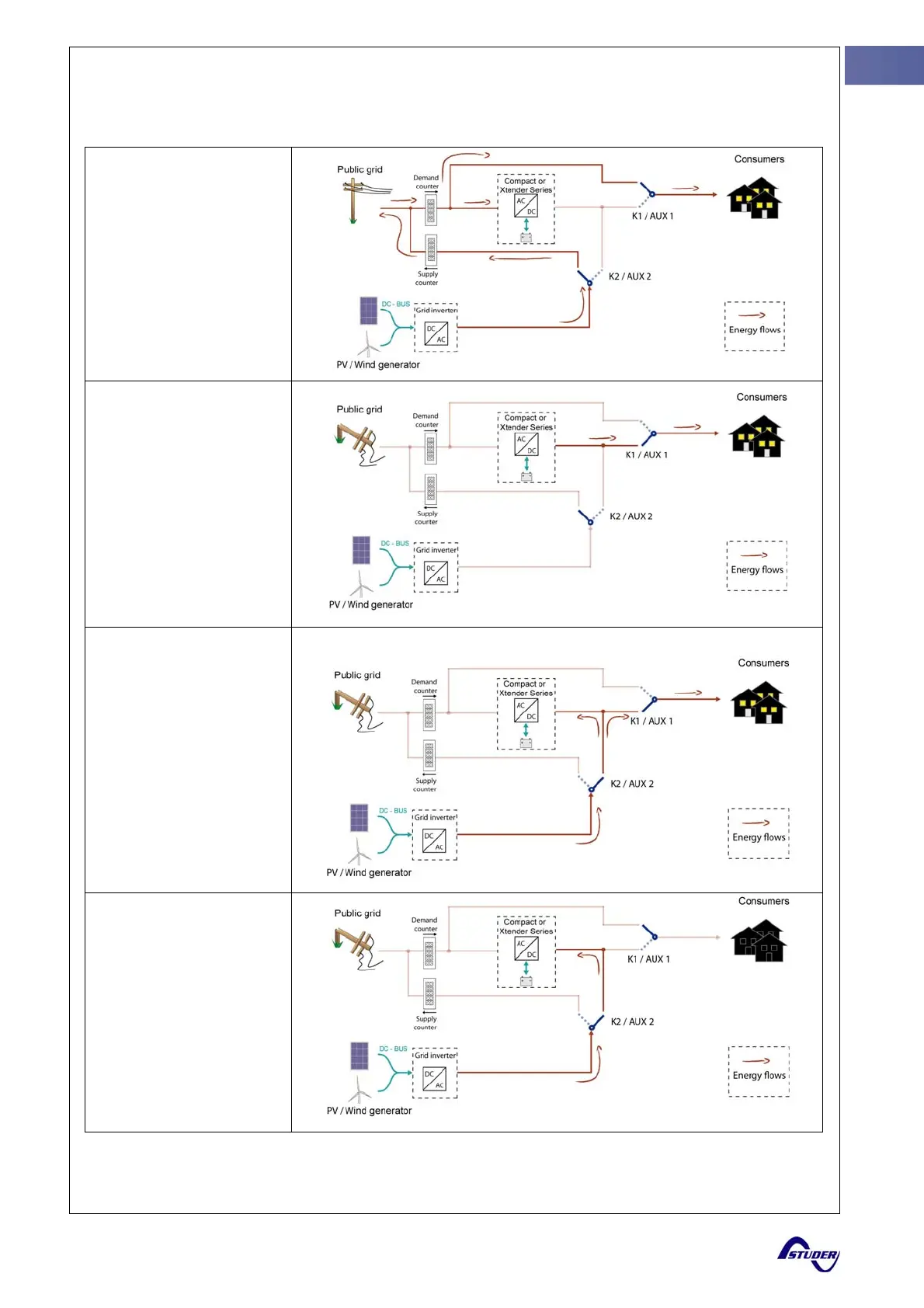
The Solsafe concept can be described by these four different situations
i
The grid is present
K1 / AUX1 is in “bypass
mode”.
K2 / AUX2 is switched on
the grid (feeding grid).
The grid charges the
batteries.
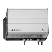
No grid and batteries
fully charged
K1 / AUX1 is in “power cut
mode”: the backup inverter
supplies the consumers
from the batteries.
K2 / AUX2 is switched on
the grid. Solar energy is not
necessary as long as the
battery is “full”.
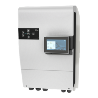
No grid and batteries
partly charged
K1 / AUX1 is in “power cut
mode”: the consumers are
supplied by the backup
inverter (batteries) and / or
solar energy.
K2 / AUX2 is switched on
the backup grid. Solar
energy is used for
supplying the consumers
and/or the batteries.(Bi-
directional output of
inverters)
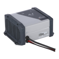
No grid and batteries
discharged
K1 / AUX1 is in “bypass
mode” and disconnects
completely the consumers.
It will switch back in “power
cut mode” when the battery
will recover a partial
charged level.
K2 / AUX2 is switched on
the backup grid. Solar
energy is used for charging
the battery.
i
K1, 2 are for Compact series and AUX1, 2 are for Xtender Series