Appendices – Page 7 / 9
Application Note 003
Appendix 5.2, Example of wiring
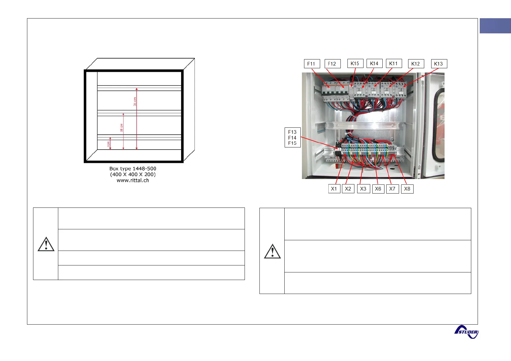
The box
The distances between the bars of support must be respected so
all components of the system can fit in the box.
This system can be connected in any electrical box whose size
permits it.
The wiring must be according to the local regulation
The bars of support are not provided by Rittal.
The assembling
At the top of the box are wired :
Relays K15, K14, K11, K12 and K13 and fuse holders F11 and
F12.
At the bottom of the box are wired :
Fuse holders F13, F14 and F15 and the terminals X1, X2, X3, X6,
X7 and X8
The cables must be wired as close as possible to relays and
contacts to leave a place for the ENS 31