CyberOne EC CW IOM Manual
8
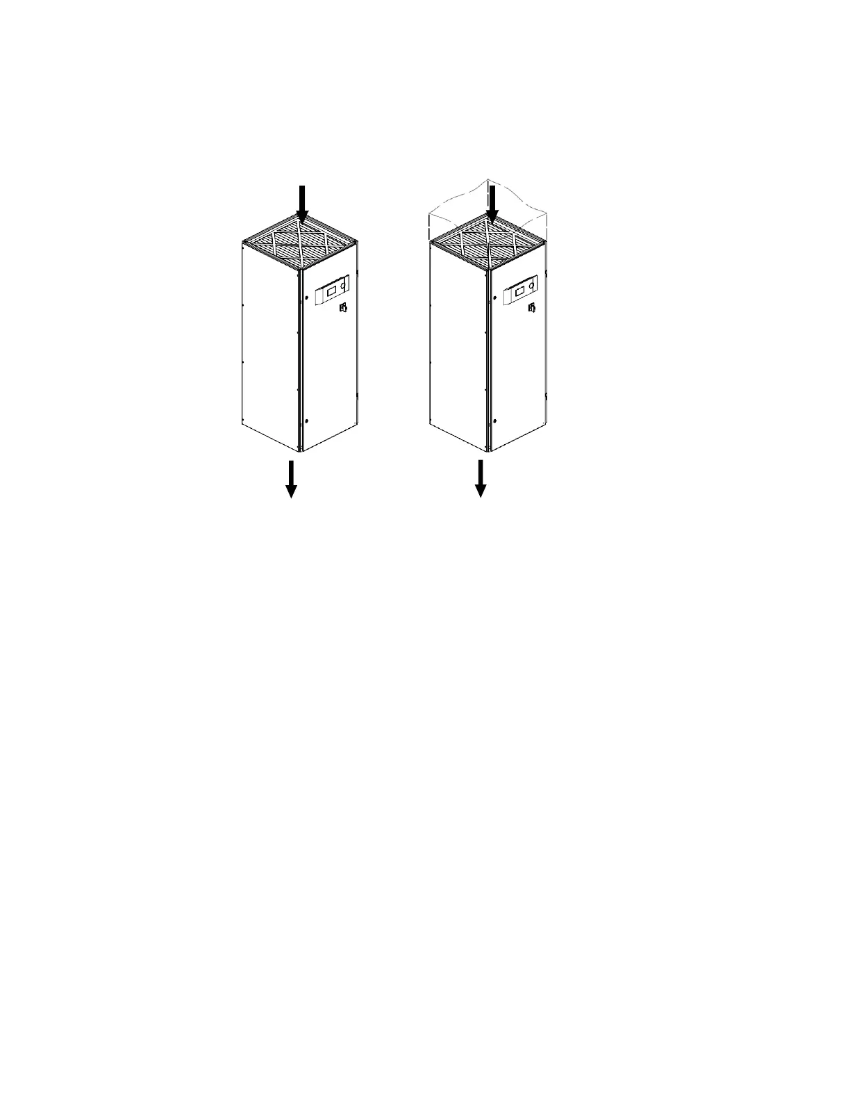
Figure 4. Downflow Configuration Typical Air Patterns
2.5 Air Distribution Connection
2.5.1 Downflow Configuration Air Patterns
In a downflow unit, the conditioned supply air discharges through the bottom of the unit, typically into a raised floor. There are
two basic return air patterns: top free return and top ducted return (see Figure 4).
If ductwork is to be installed, always consult your local and state codes to determine ducting requirements. The duct system
should be designed to allow the air to move with as little resistance as possible.
The return inlet is provided with flanges for connecting ductwork. Refer to the installation drawing provided with the unit.
Ductwork may be connected with either pop rivets or self-tapping screws.
2.5.2 Upflow Configuration Air Patterns
In a configured unit, the conditioned supply air has two methods of discharge: Ducted or through a 2- or 3-way grilled
discharge plenum box (see Figure 5). There are two basic air patterns: front free return and rear ducted return. Consult your
local or state codes to determine ducting requirements before ducting the unit. The duct system should be designed to allow
the air to move with as little resistance as possible.
Supply air outlets and the rear ducted return are provided with flanges for connection of the ducting. Refer to the installation
drawing provided with the unit. Ductwork may be connected with either pop rivets or self-tapping screws.