CyberOne EC CW IOM Manual
10
2.6 Optional Equipment (Field Installed)
NOTE
Do not mount any optional equipment on the unit
access doors.
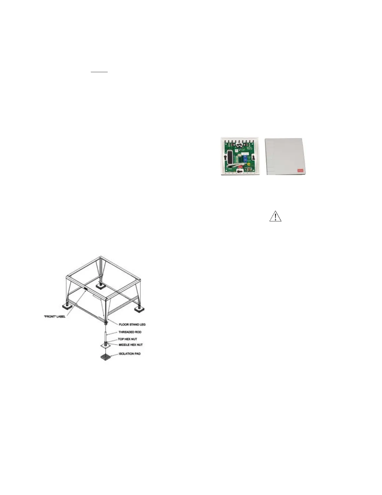
2.6.1 Floor Stand
Install the floor stand (see Figure 6) directly on the sub-floor
on the isolation pads supplied, ensuring the side with the
FRONT label is facing the same direction as the front of the
precision A/C unit. Refer to the floor stand assembly
drawing for the dimensions required to cut the raised floor.
The optional floor stand is designed with adjustable feet on
all the legs allowing for leveling and overall height adjustment.
Refer to the floor stand assembly drawing for minimum and
maximum height adjustability of your floor stand. To adjust
the height, first loosen the middle hex nuts on each leg. Next,
turn the top hex nuts to raise or lower the floor stand. Once
the floor stand is level and even with the raised floor, lock all
feet in place by tightening the middle hex nuts against the
top hex nuts.
2.6.2 Remote Controller Terminal
As an option, the E² controller terminal may be remotely
mounted. Refer to the system drawings and supplemental
controller manual sent in the data package with your unit for
mounting and wiring instructions.
Figure 6. Optional Floor Stand Installation
2.6.3 Remote Temperature/Humidity
Sensor
The remote temperature/humidity (T/H) sensor must be
located so that it will properly sense the temperature/
humidity conditions to be controlled. The T/H sensor should
not be mounted near a doorway or an area where it would be
exposed to direct sunlight. When locating the sensor, consider
the length of wire to be used. As an option, a 75 foot or 150
foot long cable may be provided by. Follow the steps below
to mount the sensor.
Temperature /Humidity Sensor
1. Remove the cover from the base of the sensor by squeez-
ing it at the top and bottom.
CAUTION
Take care not to damage the exposed temperature/
humidity sensors on the PC board when the cover is
removed. The sensors can be damaged if handled
improperly.
2. Temporarily place the base against the mounting sur-
face.
3. Level the base. Mark and drill mounting holes through at
least two of the available slotted holes.
4. Run a 3-conductor shielded cable through the opening
in the base, then secure the base with screws ensuring
the word TOP on the PC board is oriented upward.
5. Make the wiring connections. Refer to “2.8 Utility Con-
nections” on page 12 and the wiring diagram supplied
with your unit.
6. Seal the hole in the wall behind the sensor.
7. Replace the cover plate on the base.
2.6.4 Remote Water Detector
The remote water detector is normally placed on the sub-floor
or in a field-supplied auxiliary drain pan located beneath the
unit. provides two types of water detectors, installed as
follows: