2
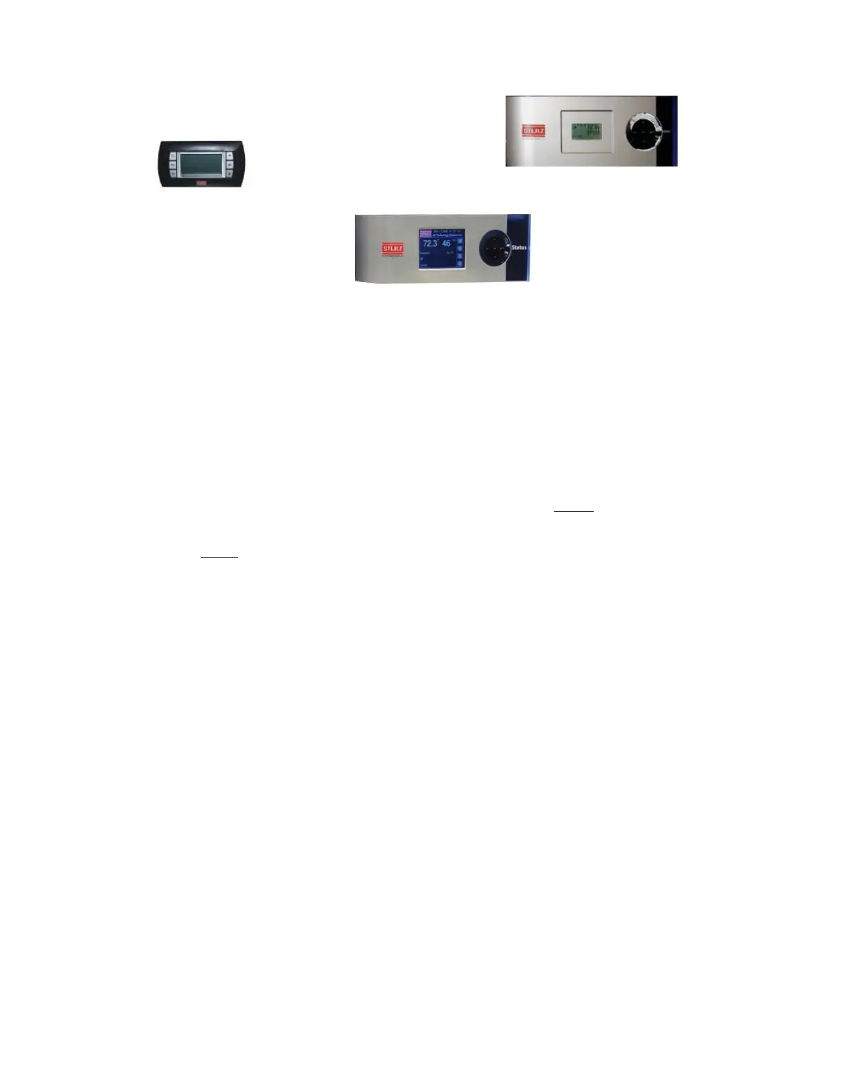
E2 Terminal — Large Bezel
E
² Terminal Small Bezel (Remote Only)
E2 Terminal — Touch Screen
1.3 Product Description
The CyberOne EC CW system comes in two cabinet sizes: A
compact 30.6 inches wide by 30.6 inches deep cabinet for
units ranging from 12 – 17.5 kW (42 – 60 MBH) and a 48
inches wide by 34 inches deep cabinet for units ranging from
28 – 35 kW (96 – 120 MBH).
The system is available in two airflow patterns: Upflow and
downflow. Cabinet height is determined by these airflow
patterns. See the STULZ CyberOne EC Chilled Water
Engineering Manual for cabinet dimensions, with and
without the optional discharge plenum box assembly.
NOTE
The CyberOne EC CW system is designed to supply
air to only one room.
The system’s functional modes of operation, in addition to
cooling, are heating, humidification and dehumidification,
which provide complete environmental control of a
conditioned space.
An advanced
E² series microprocessor controller is mounted
inside the CyberOne EC CW electric box. This controller
provides superior features for comprehensive control of the
unit. These features include: a full alarm system; input/output
monitoring status; full integrated control of heating, cooling,
humidification, and dehumidification; multi-A/C unit control;
and remote communication with building management
systems.
The E² user interface terminal is typically factory mounted
on the front access door of the unit. As an option, the small
bezel terminal may be shipped loose for remote mounting to
a wall or control panel.
An operating manual for the system controller is provided
under separate cover. Refer to that manual for detailed
instructions on operating the system controller provided
with your unit.
1.4 General Design
The CyberOne EC CW is housed in a steel frame type cabinet
and is rated for indoor use. The exterior of the cabinet is
coated with a powder coat finish to protect against corrosion.
A hinged door is located in the front of the cabinet for easy
access to all components. Operator controls are conveniently
located on the front of the cabinet.
NOTE
Customer specified non-standard features or
design variations may not be described in this
manual. Refer to the installation and/or electrical
drawings supplied with your unit for details on
additional feature(s). In some cases, an addendum
to this manual may also be included to further
describe the feature(s).
Figure 1 depicts the internal layout of a typical CyberOne
EC CW downflow unit and identifies the major
components. The location of major components vary
depending on the model number and options purchased.
Figure 2 depicts a typical internal layout of a typical
CyberOne EC CW upflow unit and identifies the major
components. The location of major components vary
depending on model number and options purchased.
1.4.1 Electric Box
The unit’s electrical components are mounted in the electric
box behind a front hinged access door. The access door is
safety interlocked with the main power service disconnect
switch (See Figure 1 and Figure 2), preventing the door from
opening when the switch is in the On position. The switch must
be set to Off to gain access to the electric box.