10 11.8.22 © STULZ USA – all rights reserved
CYBERWALL™ INSTALLATION, OPERATION AND MAINTENANCE MANUAL
Electric Box Access
Electrical components are divided between a main electric box housed behind a hinged access door in the
bottom module, and an auxiliary electric box housed behind a hinged access door in the top module, as
shown in Figure 2. Each door is secured by three turnlock fasteners that are rotated to latch/unlatch the door.
The main electric box contains the main power service disconnect switches that turn power to the unit on and
off (see Figure 2).
Fans
The unit is equipped with six high efficiency fans. All fans are direct-drive backward incline impeller designs.
There are four options for the fans:
• EC Titanium, 5 HP AC motor with incorporated VFD for speed control
• EC Titanium, 7.5 HP AC motor with incorporated VFD for speed control
• AC Induction, 5 HP AC motor with a single VFD for control
• AC Induction, 7.5 HP AC motor with a single VFD for control
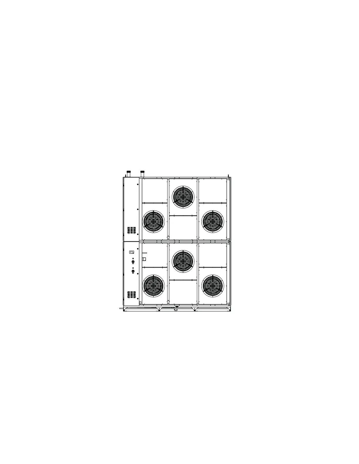
FRONT VIEW WITH FILTER RACKS REMOVED
Figure 3. Fan Configuration
Chilled Water Connections
Water coil connections are made through two 2½ inch pipes located at the top left corner of the upper
module (when viewed from the front - see “Figure 2. Unit Cabinet Features” on page 9). Connections can be
made using copper sweat, rolled groove, or copper female-threaded pipes.
Temperature/Humidity Sensors
A temperature/humidity (T/H) sensor is factory mounted on the return side of the unit. The T/H sensor
monitors the return air conditions and provides input signal(s) to the system controller to manage the
operation of the air conditioning (A/C) unit consistent with the set points entered in the controller.
 Loading...