-SCS CONDENSER IOM MANUAL
6
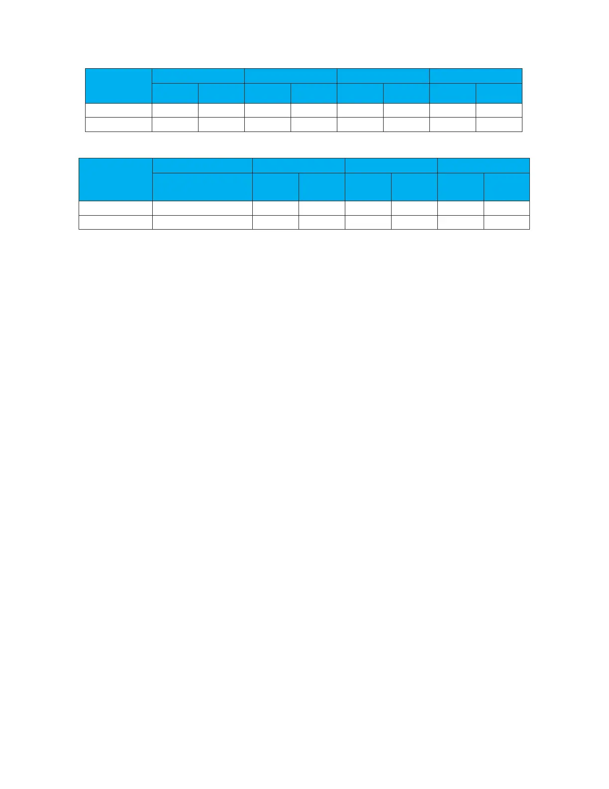
Table 1. Fan Cycling Pressure Control Settings
Cut-in Cut-out Cut-in Cut-out Cut-in Cut-out Cut-in Cut-out
R407C 320 psig 240 psig 330 psig 250 psig 340 psig 260 psig 345 psig 265 psig
Table 2. Variable Fan Speed Control Settings
Min. Max.
Cut-in Cut-out Cut-in Cut-out Cut-in Cut-out
R407C 240 315 325 psig 255 psig 340 psig 260 psig 345 psig 265 psig
1.5.3 Flooded Head Pressure Control
Used for outdoor installations where ambient condenser air inlet temperatures may fall to -30°F, flooded head pressure
control is used to maintain head pressure during the low ambient temperature conditions. A head pressure control valve
and a receiver are used in the refrigeration circuit to back up liquid refrigerant into the condenser coil. The head pressure
control valve is a 3-way modulating valve controlled by the discharge pressure (see Figure 3). The head pressure control
valve and the receiver may be located with the RCU or with the indoor evaporator unit.
When the A/C unit begins to operate, the discharge pressure rises. When the pressure reaches the “1st Fan” pressure
control setting (Table 1), the condenser fan is cycled on as described in 1.5.1. If multiple fans are used, they will operate
by pressure fan cycling.
When ambient temperature drops, the discharge pressure drops also. When the discharge pressure drops, the head
pressure control valve diverts discharge gas away from the condenser to the receiver. Liquid flow from the condenser
is restricted, causing liquid to back up in the condenser.
Flooding the condenser reduces the area available for condensing. The desired result is to increase the pressure into
the condenser, maintaining a minimum discharge pressure during low ambient operation thus ensuring proper
condensing temperature. The head pressure control valve requires no adjustment.
This method of controlling head pressure allows the condenser fan to run continuously. While the fan is running, the
flooded head pressure control valve modulates the amount of discharge gas entering the receiver. As the pressure
increases, the valve diverts more discharge gas to the condenser, allowing more liquid to flow from the condenser to the
receiver.
When using this method of head pressure regulation there must be enough refrigerant in the system to ensure an
adequate charge at the lowest expected ambient temperature in which the system will be operating. A receiver is used to
store the extra refrigerant when the condenser is not utilizing it.