CONDENSER IOM MANUAL
13
2.5.3 Receiver Pipe Installation
(SCS condenser only)
Receiver inlets and outlets are equipped with RotoLock
valves that must have brazed pipe connections. It is
important to remove the valve from the adapter on the
receiver before brazing the refrigerant piping to it. Wrap wet
rags around the valve body to prevent the internal parts from
being damaged by the heat.
After brazing the pipe to the valve, remove and replace the
Teflon O-ring in the RotoLock adapter with the new one
which is cable-tied to the valve. When re-attaching the valve
to the receiver, apply thread lock to the adapter threads to
prevent it from vibrating loose. Tighten the valve to the
receiver and check it for leaks when performing the steps in
2.7.3 Preparing System for Charging on page 17.
2.6 Utility Connections
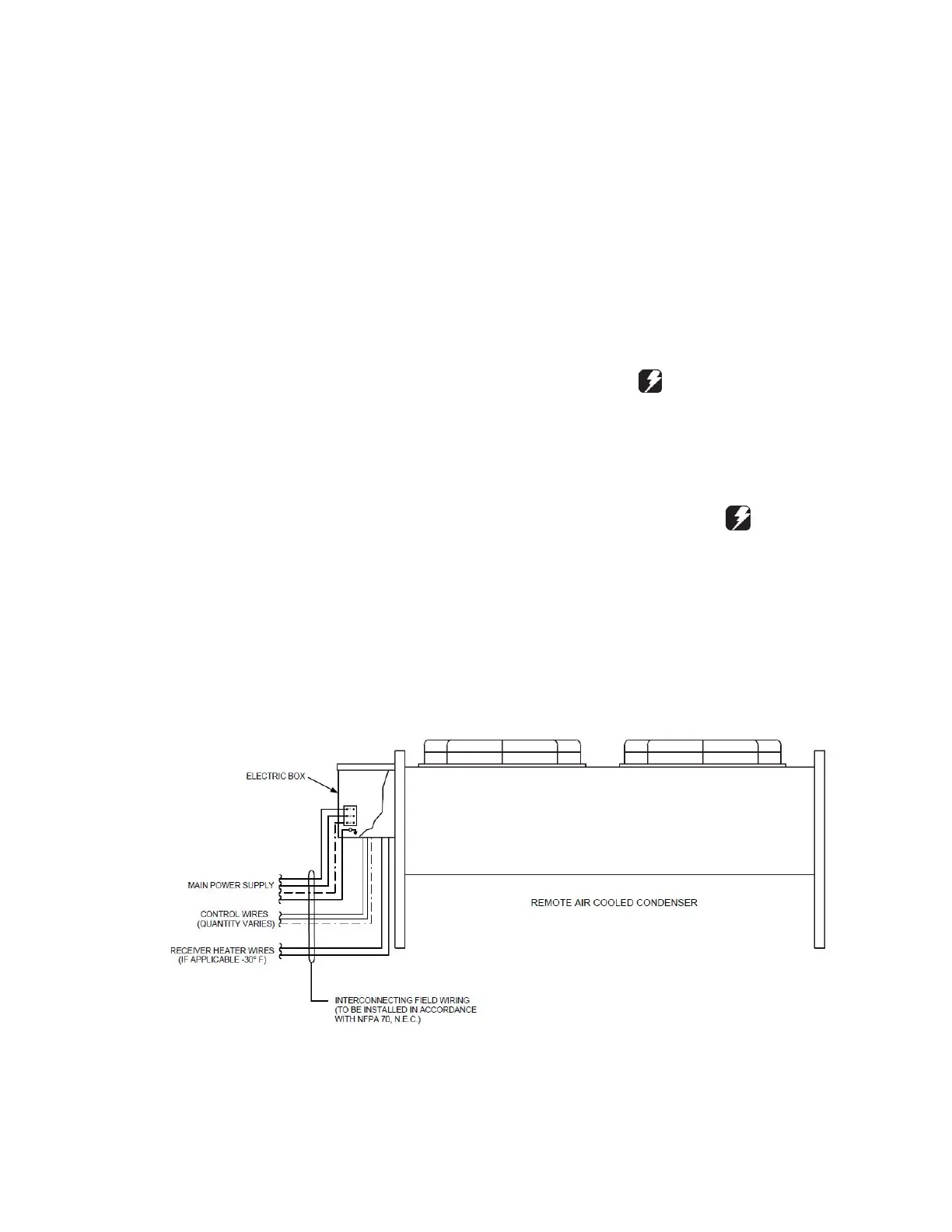
2.6.1 Main Power and Control Wiring
Systems equipped with a remote condenser require field
wiring (see Figure 10). The installer must provide main power
wiring to the remote condenser control box. The condenser is
provided with main power and control terminal positions for
connection of the field wiring (supplied by others). Additional
conductors may be necessary depending on options selected.
Verify that the main power supply coincides with the voltage,
phase and frequency information specified on the system
nameplate (see Figure 11). The supply voltage measured at
the unit must be within ±10% of the voltage specified on the
nameplate. The nameplate also provides the full load amps
(FLA), the current that the unit will draw under full design
load, the minimum circuit ampacity (MCA) for wire sizing, and
the maximum fuse or HACR (Heating, Air Conditioning,
Refrigeration) breaker size (MAX FUSE/CKT BKR) for
circuit protection. The unit’s nameplate is located inside the
electrical box.
Pilot holes or electrical knock-outs for the conduit are in the
bottom of the electric box. A label stating MAIN POWER
INPUT is nearby. The main power wires are terminated at the
line side of the service disconnect switch located within the
electric box. A separate equipment ground lug is provided
within the electrical box for termination of the earth ground
wire.
WARNINGS
High voltage is used in the operation of this
equipment. Death on contact may result if personnel
fail to observe safety precautions.
The control transformer supplied with the equipment is sized
and selected based upon the expected load for the system.
CAUTION
Do not connect any additional loads to the system control
transformer. Connecting additional loads to the factory
supplied control transformer may result in overloading of the
transformer.
Figure 10. Field Wiring