Built-In
Built-In
(600-
(600-
2
2
)
)
Series
Series
Icemaker Information
6-5
#3758407 - Revision B - August, 2006
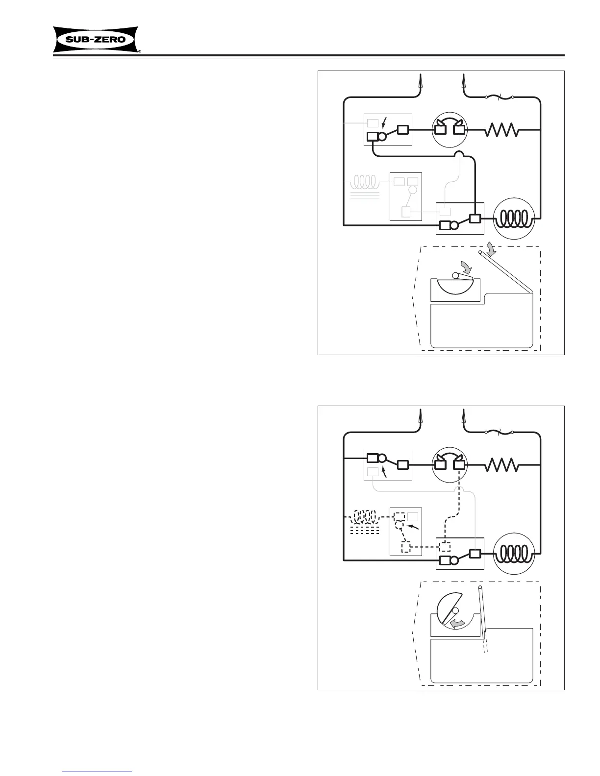
First Revolution Continued (See Figure 6-5)
• The ice ejector reach the ice in the mold.
• The ice releases from the mold as the ejector
blades begin to rotate the cubes out.
• The drive motor remains energized through the
holding switch.
• The mold heater remains energized through the
thermostat.
• As the shut-off arm rises, the shut off switch is
tripped to “normally closed”, and then the shut-off
arm begins to lower.
Figure 6-5. First Revolution Continued
APPROXIMATE POSITION
OF ICE EJECTOR AND
ICE LEVEL ARM
DURING OPERATION
115 VOLTS
60 CYCLES
SHUT-OFF SWITCH
THERMOSTAT
MOLD HEATER
WATER
SOLENOID
SOLENOID SWITCH
MOTOR
HOLDING SWITCH
NO
NC
C
NC
NC
NO
NO
C
C
TCO
ICE MOLD
ICE BUCKET
ICE
Figure 6-6. First Revolution Continued
APPROXIMATE POSITION
OF ICE EJECTOR AND
ICE LEVEL ARM
DURING OPERATION
115 VOLTS
60 CYCLES
SHUT-OFF SWITCH
THERMOSTAT
MOLD HEATER
WATER
SOLENOID
SOLENOID SWITCH
MOTOR
HOLDING SWITCH
NO
NC
C
NC
NC
NO
NO
C
C
ICE MOLD
ICE BUCKET
ICE
TCO
First Revolution Continued (See Figure 6-6)
• The ice has released from the mold.
• The motor remains energized through the holding
switch.
• The shut-off arm is lowered and the shut off switch
is tripped to “normally open”.
• The water valve solenoid switch is tripped by the
timing cam, but the solenoid is not energized
because the thermostat is still closed and energiz-
ing the mold heater. (Electric current follows the
path of least resistance.)