Component Access/Removal
Integrated (
Integrated (
700-
700-
2) Series
2) Series
7-34
#3756780 - Revision D - July, 2005
700-2 BASE UNIT COMPRESSOR AREA
ELECTRICAL AND MECHANICAL
COMPONENTS
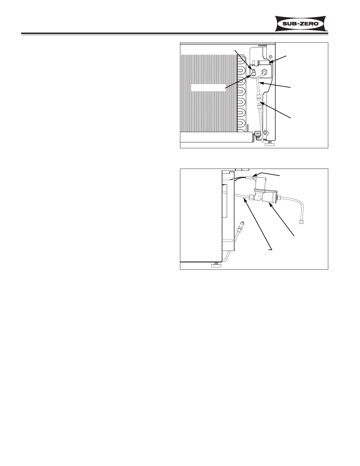
Icemaker Water Valve Removal (700BFI-2 Only)
The icemaker water valve assembly on a 700BF/I-2 is
attached to the valve bracket, which is located on the
right side of the compressor area, in front of a fiber-
glass air baffle. A screw passing through a key-hole
slot in the valve assembly secures the valve to the
valve bracket.
NOTE: It is not necessary to remove the compressor
tray to access the water valve assembly.
To access and remove the icemaker water valve, first
turn off the water supply to the icemaker. Then, remove
the kickplate/grille. With a wrench, disconnect the
brass compression fitting which holds the water supply
line to the water inlet stub. With a Phillips screwdriver,
loosen the screw that secures the valve assembly to
the valve bracket. Grab the water inlet stub and lift up
so that the head of the screw lines up with the large
section of the key-hole slot. Pull the valve assembly
forward until the screw clears the key-hole slot, then
lower the assembly down until the valve body clears the
valve bracket and pull the assembly out from the com-
pressor area. (See Figure 7-87) Now, unplug the elec-
trical leads, and disconnect the outlet tube plastic com-
pression fitting with a wrench. (See Figure 7-88)
Figure 7-87. Water Valve Removal, BF/I-2
Figure 7-88. Disconnect Water Valve, BF/I-2
Key-Hole Slot
Water Valve
Inlet Stub
Compression
Fittings
Outlet Tube
Electrical Leads
Screw
Water Valve