Component Access/Removal
Integrated (
Integrated (
700-
700-
2) Series
2) Series
7-36
#3756780 - Revision D - July, 2005
Drain Tube Heater Removal (700BF/I-2 Only)
The electrical connections for the 700BF/I-2 drain tube
heater are located at the back of the compressor area
with the heater leads entering the sump drain tube from
the compressor area.
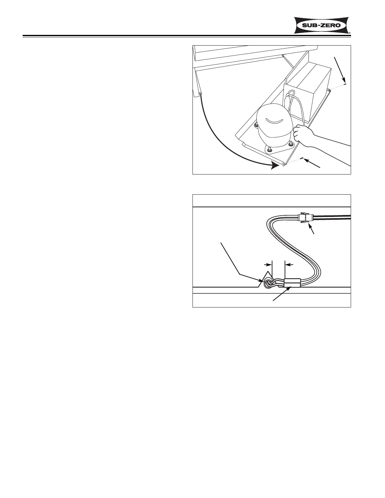
To access and remove the drain tube heater, the kick-
plate/grille will need to be removed first and the unit
tray will need to be slid out. To slide the unit tray out,
extract the two screws that secure the tray to the unit,
located at the front right and left corners. Grab the front
flange of the tray and pull forward. (See Figure 7-92)
NOTE: It may be necessary to disconnect the com-
pressor electrical leads in order to pull the tray out far
enough to access the drain tube heater.
Unplug the drain tube heater electrical leads and pull
the heater from the drain tube (See Figure 7-93).
NOTE: When installing the replacement drain tube
heater, push the heater leads into the sump drain tube
until splices are 2-1/2” from drain tube outlet (See
Figure 7-93). Also, it is recommended to remove the
sump cover to make sure the drain tube heater has slid
under the evaporator.
Figure 7-93. Drain Tube Heater in Compressor Area
Figure 7-92. Sliding Unit Tray Out
Screw
Screw
Drain Tube
Heater Electrical
Connection
Heater Leads
In Drain Tube
Splices
2-1/2”