Electronic Control
Integrated (
Integrated (
700-
700-
2) Series
2) Series
3-9
#3756780 - Revision D - July, 2005
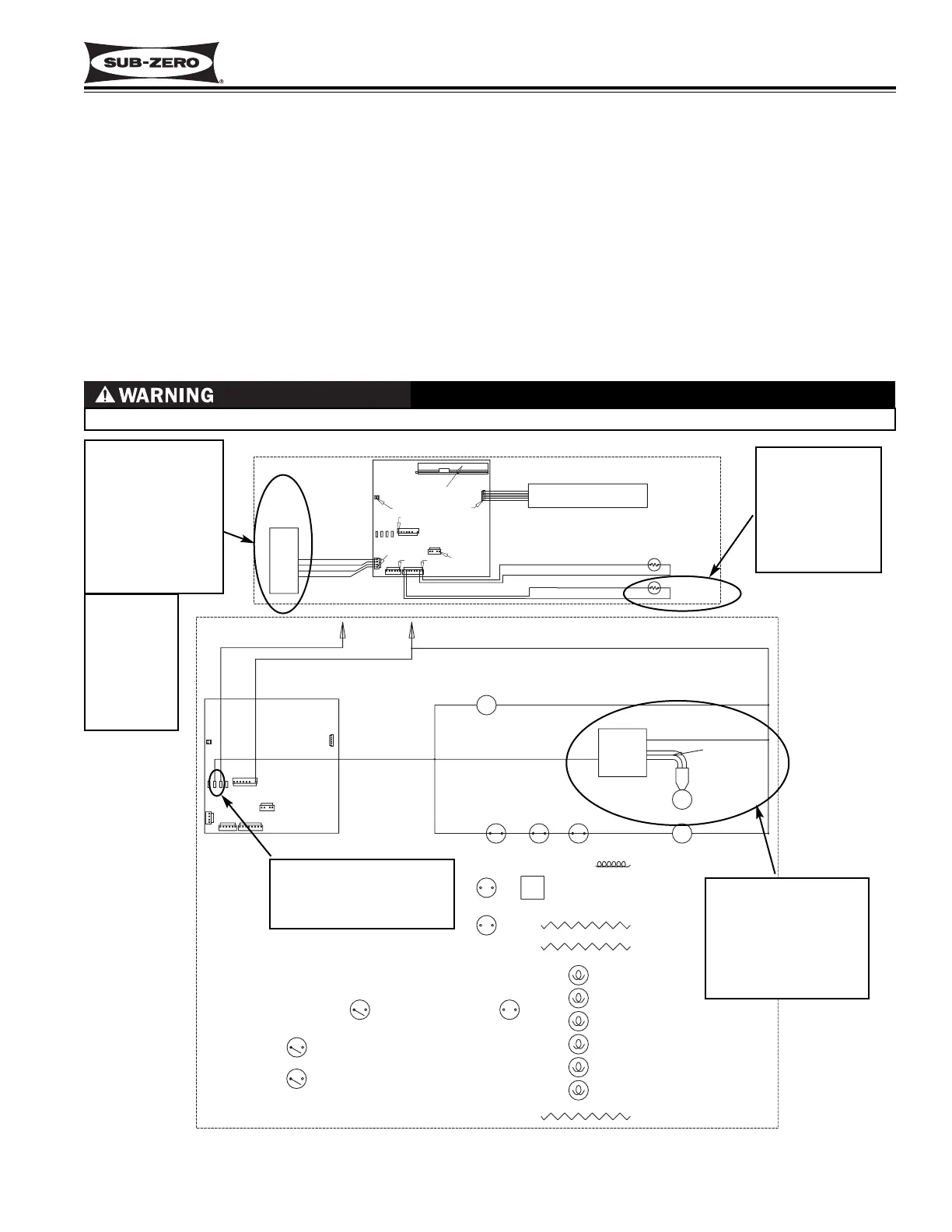
Control Variable Speed Compressor (700TF/I-2V)
Like other tall units, the temperature signal from the thermistor in a 700TF/I-2V freezer compartment is monitored by
the microprocessor and then displayed on the LCD, and when cooling is called for, the evaporator fan and condens-
er fan are energized. But, in a model 700TF/I-2V an additional component, the compressor controller, is used to
control the variable speed compressor. How this works is, the temperature difference between the compartment
thermistor and the set-point is monitored by the microprocessor to determine the appropriate speed signal which is
then sent via a low voltage line to the compressor controller. The compressor controller supplies a 230 volt AC, 3-
phase, 50 - 150 Hz signal, based on the speed signal from the microprocessor, to the compressor. This signal caus-
es the compressor to run at varying speeds. (See Figure 3-12) Speed commands will vary at 0, 1600, 1700, 1800,
2100, 2200, 2400, 2700, 3600 and 4000 RPM, depending on compartment temperature and set-point.
NOTE: In the model 700TF/I-2V, the compressor, evaporator fan and condenser fan will run a great majority of the
time. This is normal. These components will only cycle off during defrost and may also cycle off for short periods of
time if the ambient temperature is low enough.
LT. BLUE
Figure 3-12. 700TF/I-2V Signal Trace Schematic of Variable Speed Compressor Operation
VOLTAGE EXCEEDING 200 VOLTS MAY BE PRESENT AT COMPRESSOR & COMPRESSOR CONTROLLER!
1. Compartment
temperature
monitored by
microprocessor
3. Low voltage
speed signal sent
from micro-
processor to con-
troller, based on
difference
between compart-
ment temperature
and set-point
4. Controller supplies
230 volt AC, 3-phase,
50 - 150 Hz signal
(based on the speed
signal from micro-
processor), to com-
pressor.
2. 115 Volts AC supplied to
controller, evaporator
fan, and condenser fan
when cooling is required.
NOTE: con-
troller also
sends signal
back to micro-
processor
indicating
compressor
speed status.
 Loading...


