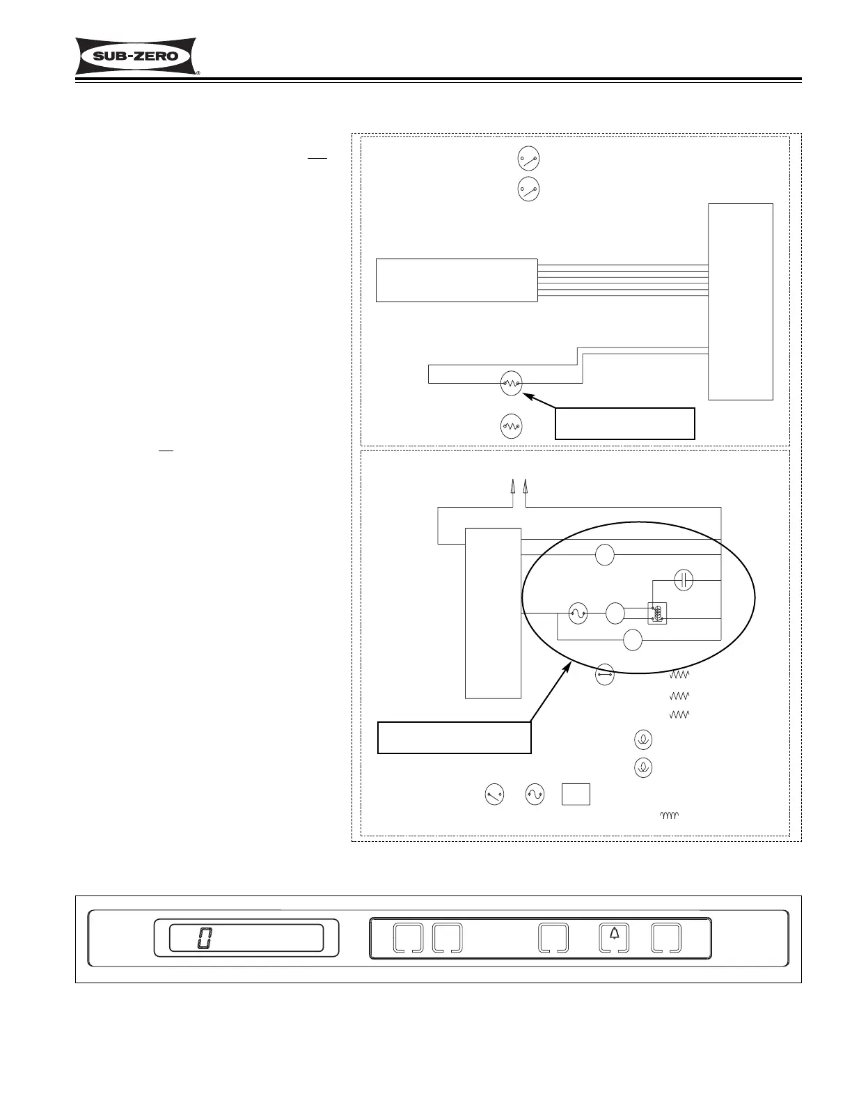
LT. BLUE W/YELLOW
LT. BLUE W/YELLOW
Figure 3-79. Signal Trace Schematic (High & Low Voltage) of
700BF/I-2 Calling for Cooling
The two drawers of the 700BF/I-2 are con-
sidered one compartment/zone. It is not
possible to set two different set-points for
the individual drawers.
The temperature signal from the thermis-
tor in the upper reed switch is monitored
by the microprocessor, and displayed on
the LCD. Though the compartment air
temperature does fluctuate, the LCD dis-
plays the average temperature (See
Figure 3-80). When the compartment
temperature reaches high offset, the
microprocessor supplies power to the
evaporator fan, compressor and condens-
er fan. (See Figure 3-79). When the
compartment temperature reaches low off-
set, the microprocessor interrupts power
to the compressor and evaporator fan,
cycling them of
f.
NOTE: If the compartment temperature
should ever exceed either the high offset
or low offset (example: when a door is left
open), the temperature displayed on the
LCD will change by one degree per
minute.
High offset temperature
detected
Evap fan, compressor and
condenser fan energized
Monitor, Regulate and Display Temperatures in the 700BF/I-2