Component Access/Removal
Integrated (
Integrated (
700-
700-
2) Series
2) Series
7-15
#3756780 - Revision D - July, 2005
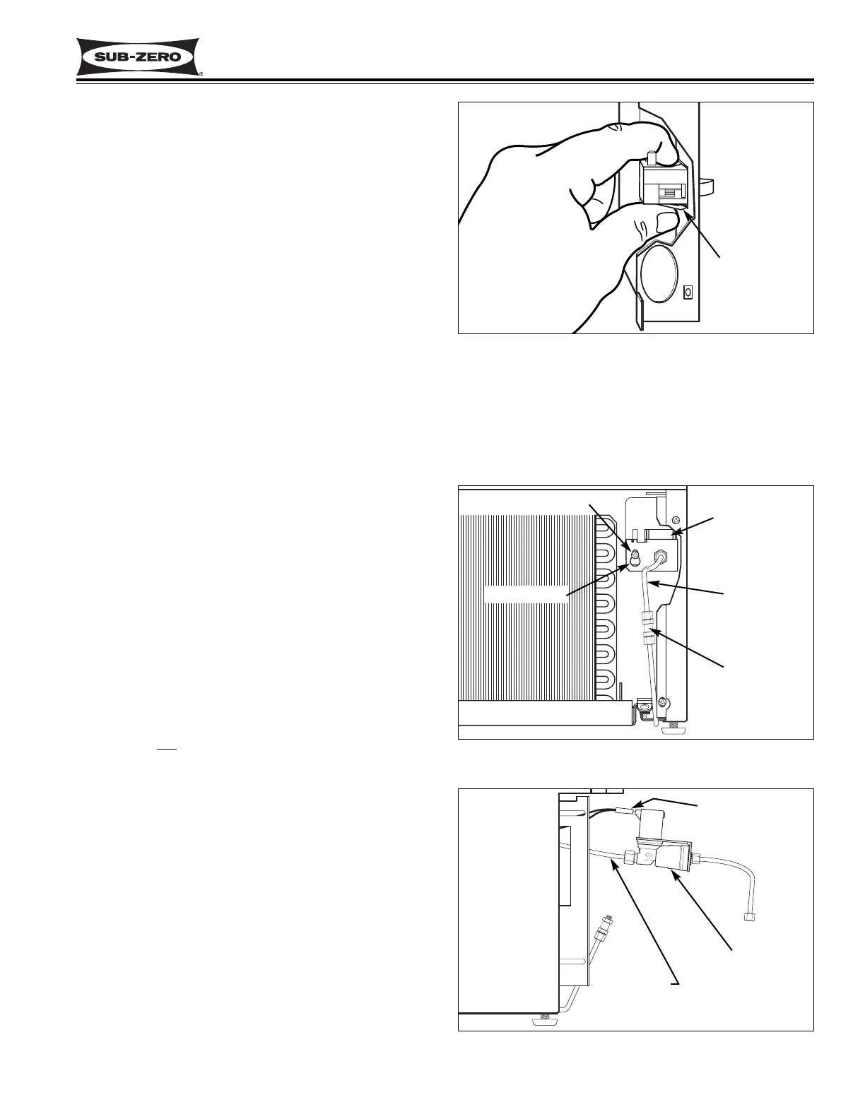
Figure 7-36. Lower Compartment Switch Removal
Lower Compartment Light Switch / Fan Switch /
Icemaker Switch Removal (All Tall Units)
The light switch, fan switch and the icemaker switch in
the lower section of all tall units are mounted to the
switch enclosure. The switches are held in place by
tabs on the sides of the switches.
To access and remove a switch, first remove the two
drawers, the heat exchanger cover, the lower evapora-
tor cover and the switch enclosure. Then, unplug the
electrical leads from the switch being removed.
Depress the tab on the side of the switch and push the
switch out from the enclosure. (See Figure 7-36)
700-2 TALL UNIT COMPRESSOR AREA
ELECTRICAL AND MECHANICAL
COMPONENTS
Icemaker Water Valve Removal
(700TCI-2, 700TFI-2, 700TFI-2V)
The icemaker water valve assembly is attached to the
valve bracket, located on the right side of the compres-
sor area, behind a fiberglass air baffle. A screw passing
through a key-hole slot in the valve assembly secures
the valve to the valve bracket.
NOTE: It is not
necessary to remove the compressor
tray to access the water valve assembly.
To access and remove the icemaker water valve, first
turn off the water supply to the icemaker. Then, remove
the kickplate/grille. With a wrench, disconnect the
brass compression fitting which holds the water supply
line to the water inlet stub. Push the fiberglass air baf-
fle out of the way. With a long Phillips screwdriver,
loosen the screw that secures the valve assembly to
the valve bracket. Grab the water inlet stub and lift up
so that the head of the screw lines up with the large
section of the key-hole slot. Pull the valve assembly
forward until the screw clears the key-hole slot, then
lower the assembly down until the valve body clears the
valve bracket and pull the assembly out from the com-
pressor area. (See Figure 7-37) Now, unplug the elec-
trical leads, and disconnect the outlet tube plastic com-
pression fitting with a wrench. (See Figure 7-38)
Depress tabs
on switch and
push from the
enclosure
Figure 7-37. Water Valve Removal, TC/I-2, TF/I-2
Figure 7-38. Disconnect Water Valve, TC/I-2, TF/I-2
Key-Hole Slot
Water Valve
Inlet Stub
Compression
Fittings
Outlet Tube
Electrical Leads
Screw
Water Valve