Integ rated Installation 18
Panel Insta llation
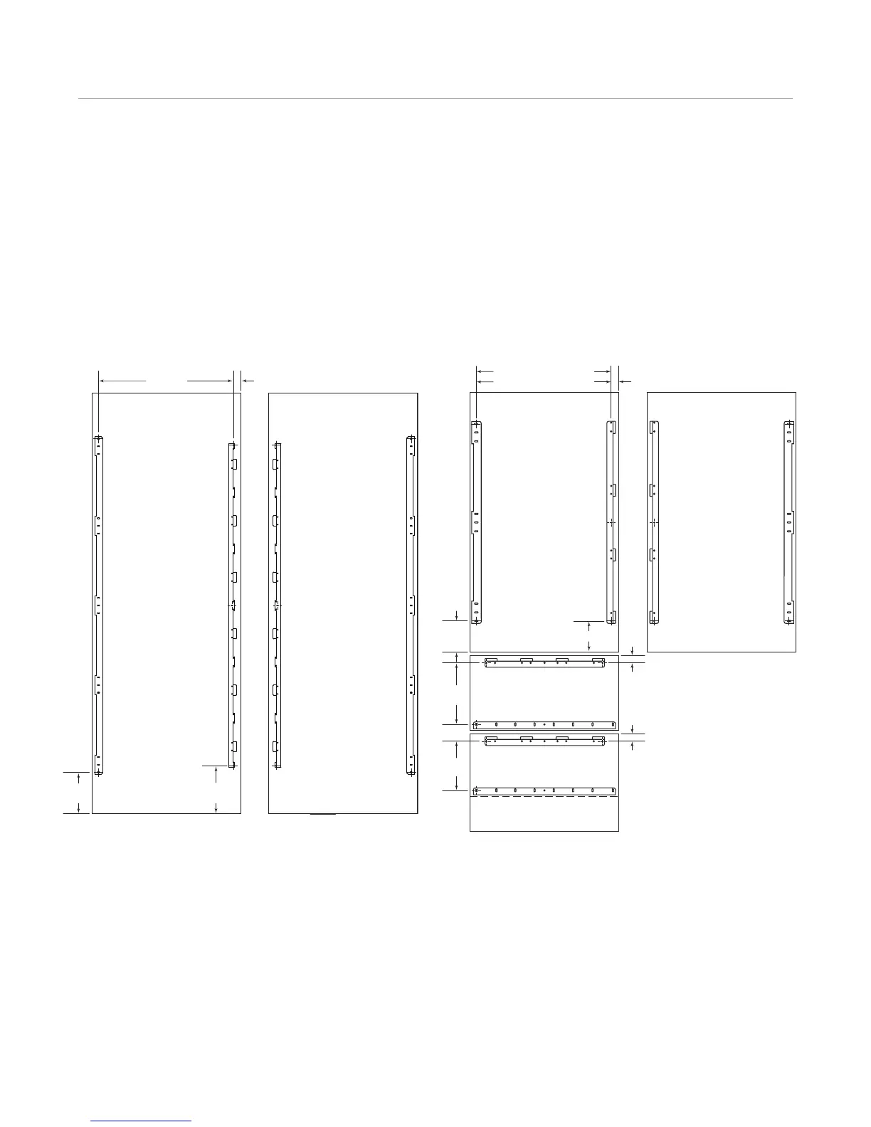
PANEL BRACKET POSITIONING
The illustrations below show placement of pane l mounting
brackets. Dimensions are based on a 4"
(102) toe kick and
a
1
/8" (3) reveal. A reveal of up to
1
/4" (6) is possible, but
panel dimensions need to be adjusted accordingly.
5
3
/16" (132)
5
5
/16"
(135)
8
7
/16"
(214)
11
5
/16"
(287)
1
1
/4"
(32)
1
1
/4"
(32)
23
7
/8" (606) FOR 27" UNITS
3
2
7
/8" (835) FOR 36" UNITS
LH DOOR SWING
BACK OF PANEL
RH DOOR SWING
BACK OF PANEL
BACK OF PANEL
BACK OF PANEL
1
7
/16" (37)
8
11
/16"*
(221)
7
3
/16"*
(183)
24" (610)
1
13
/16" (46)
LH DOOR SWING
BACK OF PANEL
RH DOOR SWING
BACK OF PANEL
*Dimensions are based on a 4" (102) toe kick.
COLUMN MODELS TALL AND DRAWER MODELS