Icemaker Operation
Integrated (
Integrated (
700-
700-
2) Series
2) Series
6-4
#3756780 - Revision D - July, 2005
MODULAR ICEMAKER TEST PROCEDURES
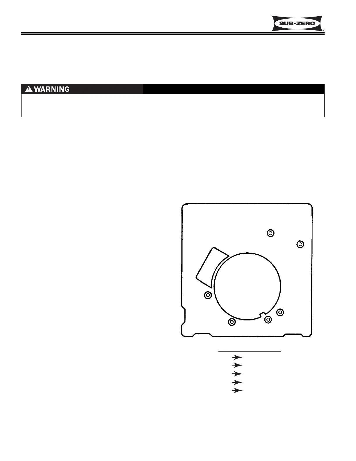
Perform the following tests if the icemaker is thought to be defective. See Figure 6-3 for icemaker test port loca-
tions. Test 1 through 5 are performed with 115 Volts AC supplied to the icemaker, so read the “WARNING” below
and the “additional Ice Production Notes” on the previous page before proceeding.
ELECTRIC SHOCK HAZARD! TESTS 1 THROUGH 5 ARE PERFORMED WITH 115V AC SUPPLIED TO THE
ICEMAKER. CARE MUST BE TAKEN WHEN PERFORMING THESE TESTS TO AVOID SEVERE PERSONAL
INJURY OR DEATH.
Voltage Tests
1. Check for 115 Volts AC between ports “L” and “N”. Make sure test probes go into test ports 1/2”.
2. Strip 1/2” of insulation from each end of a 3” piece of insulated 14 gauge wire to create a jumper/test wire.
Insert the stripped ends of this jumper/test wire into ports “T” and “H” to bypass the thermostat.
NOTE: Do not place the jumper/test wire between any other ports as this will damage the icemaker.
If the motor doesn’t run, replace the module/motor assembly.
3. Leave the jumper/test wire in until the ejector
blades rotate to approximately 8:00 o’clock. The
mold heater should heat up. If not, see test 5
below.
4. Remove the jumper/test wire when the ejector
blades reach the 8:00 o’clock position. The
water valve should energize for 7.5 seconds
when the ejector blades rotate to approximately
11:00 o’clock. If not, repeat test 2 through 4 and
check for 115V AC to solenoid when ejector
blades rotate to approximately 11:00 o’clock. If
no voltage, check electrical connections.
Continuity Tests and Thermostat Inspection
5. With icemaker removed from the unit, check the
resistance of the mold heater between ports “L”
and “H.” Reading should be between 62 - 82
Ohms. Replace mold/heater assembly if outside
this range.
6. With the module/motor separated from the
mold/heater assembly, check the resistance of
the motor between ports “L” and “M.” Reading
should be between 3390 - 4410 Ohms. Replace
module/motor assembly if outside this range.
7. If icemaker passes tests 1 through 6, check for
adequate supply of Thermal-Mastic on icemaker
thermostat. If little or no Thermal-Mastic, apply
Thermal-Mastic to thermostat. If adequate sup-
ply is present, replace thermostat.
8. See General Troubleshooting Guide if icemaker
passes tests 1 through 7.
NOTE: Never attempt to turn the icemaker ejector blades by hand. Doing so will damage the icemaker
Figure 6-3. Icemaker Test Ports
 Loading...


